c.Removefilterplate(A)andinstallairsplitter(B)in
placeoffilterplate.
d.Installfilterplate(A)asshowninhorizontalrightap-
plication.
e.Removecondensatetroughs(C)andinstallonopposite
tubesheets.
f. Installhoseontoplasticspout.
7.Installhorizontalpanonrightsideofcoilassembly.
8.Slidecoilassemblyintocasing.Besurecoilbracketoneach
cornerofverticalpanengagescoilsupportrails.
9.Reinstall2 snap-inclipstocorrectlypositionandsecure
coilassemblyinunit.Besureclipwithlargeoffsetsisused
onrightsideofunittosecurehorizontalpan.
10.Removetwoovalfittingcapsfromtheleftsideofthecoil
doorandfittingpanel.
11.Removeinsulationknockoutsonrightsideofcoilaccess
panel.
12.Remove2ovalcoilaccesspanelplugsandreinstallinto
holesonleftsideofcoilaccesspanelandfittingpanel.
13.Installcondensatepanfittingcaps(fromitem10)inthe
rightsideofthecoildoormakingsurethatthecapsnaps
andseatscleanlyonthebacksideofthecoildoor.Make
surenoinsulationinterfereswithseatingofthecap.
14.Reinstallaccessfittingpanels,aligningholeswithtubing
connectionsandcondensatepanconnections.Besuretore-
installmetalclipbetweenfittingpanelandverticalcondens-
atepan.
Makesureliquidandsuctiontubegrommetsareinplacetoprevent
airleaksandcabinetsweating.
D.ManufacturedandMobileHomeHousingApplications
1.Fancoilunitmustbesecuredtothestructureusingfield-
suppliedhardware.
2.Allowaminimumof24-in(610ram)clearancefromaccess
panels.
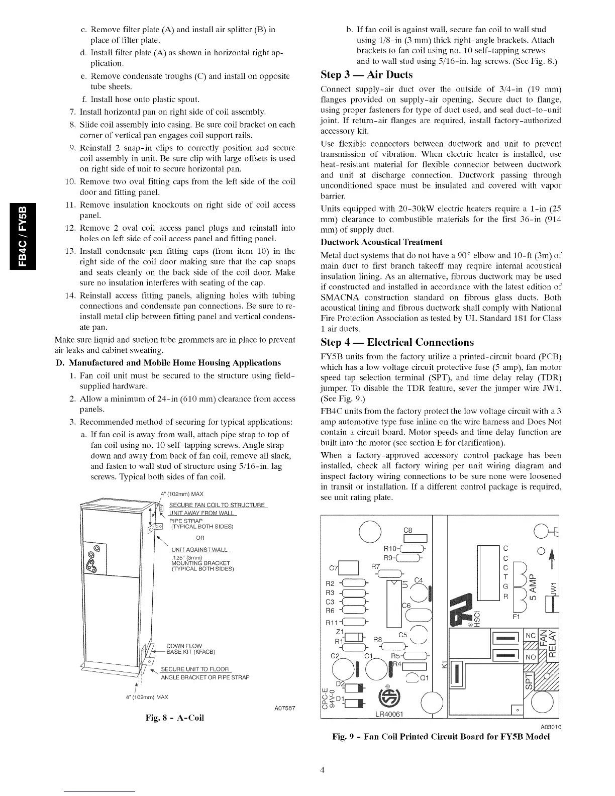
3.Recommendedmethodofsecuringfortypicalapplications:
a.Iffancoilisawayfromwall,attachpipestraptotopof
fancoilusingno.10self-tappingscrews.Anglestrap
downandawayfrombackoffancoil,removeallslack,
andfastentowallstudofstructureusing5/16-in.lag
screws.Typicalbothsidesoffancoil.
4" (102mm) MAX
SECURE FAN COILTO STRUCTURE
UNIT AWAY FROM WALL
PIPE STRAP
(TYPICAL BOTH SIDES)
OR
UNIT AGAINST WALL
.125" (3ram)
MOUNTING BRACKET
(TYPICAL BOTH SIDES)
DOWN FLOW
BASE KIT (KFACB)
_. SECURE UNITTO FLOOR
ANGLE BRACKET OR PIPE STRAP
4" (102ram) MAX
Fig. 8 - A-Coil
A07567
b. If fan coil is against wall, secure fan coil to wall stud
using 1/8-in (3 ram) thick right-angle brackets. Attach
brackets to fan coil using no. 10 self-tapping screws
and to wall stud using 5/16-in. lag screws. (See Fig. 8.)
Step 3 -- Air Ducts
Connect supply-air duct over the outside of 3/4-in (19 ram)
flanges provided on supply-air opening. Secure duct to flange,
using proper fasteners for type of duct used, and seal duct-to-unit
joint. If return-air flanges are required, install factory-authorized
accessory kit.
Use flexible connectors between ductwork and unit to prevent
transnfission of vibration. When electric heater is installed, use
heat-resistant material for flexible connector between ductwork
and unit at discharge connection. Ductwork passing through
unconditioned space must be insulated and covered with vapor
barrier.
Units equipped with 20-30kW electric heaters require a 1-in (25
ram) clearance to combustible materials for the first 36-in (914
ram) of supply duct.
Ductwork Acoustical Treatment
Metal duct systems that do not have a 90 ° elbow and 10-fl (3m) of
main duct to first branch takeoff may require internal acoustical
insulation lining. As an alternative, fibrous ductwork may be used
if constructed and installed in accordance with the latest edition of
SMACNA construction standard on fibrous glass ducts. Both
acoustical lining and fibrous ductwork shall comply with National
Fire Protection Association as tested by UL Standard 181 for Class
1 air ducts.
Step 4 -- Electrical Connections
FY5B units from the factory utilize a printed-circuit board (PCB)
which has a low voltage circuit protective fuse (5 amp), fan motor
speed tap selection terminal (SPT), and time delay relay (TDR)
jumper. To disable the TDR feature, sever the jumper wire JW1.
(See Fig. 9.)
FB4C units from the factory protect the low voltage circuit with a 3
amp automotive type fuse inline on the wire harness and Does Not
contain a circuit board. Motor speeds and time delay function are
built into the motor (see section E for clarification).
When a factory-approved accessory control package has been
installed, check all factory wiring per unit wiring diagram and
inspect factory wiring connections to be sure none were loosened
in transit or installation. If a different control package is required,
see unit rating plate.
o8 (D<
R2 <ZEZ>
C3
R6
R!1 _{_
Rlo<ZZZ_ -- c O
R9_ C
f
R7 C _
a
C6
F1
@{) }
LF:f40061
A03010
Fig. 9 - ]Tan Coil Printed Circuit Board for ]TY5B Model
 Loading...