14
Step 2 — Start--up Heating and Make Adjust-
ments
Complete the required procedures given in the Pre--Start--Up
section before starting the unit. Do not jumper any safety devices
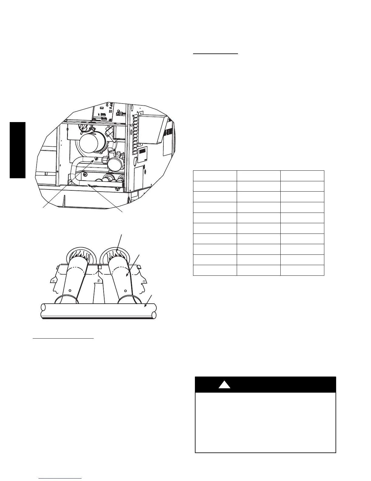
when operating the unit. Make sure that burner orifices are
properly aligned. Unstable operation my occur when the burner
orifices in the manifold are misaligned.
Follow the lighting instructions on the heating section operation
label (located on the inside of the control access panel) to start the
heating section.
NOTE: Make sure that gas supply has been purged, and that all
gas piping has been checked for leaks.
Pipe Plug
Manifold
A07679
Fig. 11 -- Burner Assembly
MANIFOLD
BURNER
BURNER FLAME
C99021
Fig. 12 -- Monoport Burner
Check Heating Control
Start and check the unit for proper heating control operation as
follows (see furnace lighting instructions located on the inside of
the control access panel):
1. Place room thermostat SYSTEM switch in the HEAT
position and the fan switch is placed in AUTO position.
2. Set the heating temperature control of the thermostat above
room temperature.
3. The induced--draft motor will start.
4. On a call for heating, the main burner should light within 5
sec. of the spark being energized. If the burners do not light,
there is a 22--sec. delay before another 5--sec. try. If the
burners still do not light, this sequence is repeated. If the
burners do not light within 15 minutes from the initial call
for heat, there is a lockout. To reset the control, break the
24--v power to W.
5. The evaporator fan will turn on 45 sec. after the flame has
been established. The evaporator fan will turn off 45 sec.
after the thermostat has been satisfied. Please note that the
integrated gas unit controller (IGC) has the capability to
automatically reduce the evaporator “ON” delay and in-
crease the evaporator “OFF” delay in the event of high duct
static and/or partially--clogged filter.
Check Gas Input
Check gas input and manifold pressure after unit start--up (See
Table 4). If adjustment is required proceed as follows:
S The rated gas inputs shown in Table 4 are for altitudes from sea
level to 2000 ft (610 m) above sea level. These inputs are based
on natural gas with a heating value of 1025 Btu/ft
3
at 0.60
specific gravity, or propane gas with a heating value of 2500
Btu/ft
3
at 1.5 specific gravity.
IN THE U.S.A.:
The input rating for altitudes above 2,000 ft (610 m) must be
reduced by 4% for each 1,000 ft (305 m) above see level.
For installations below 2,000 ft (610 m), refer to the unit rating
plate.
For installations above 2,000 ft (610 m). multiply the input on the
rating plate by the derate multiplier in Table 3 for correct input rate.
Table 3 – Altitude Derate Multiplier for U.S.A.*
ALTITUDE FT (M) PERCENT OF DERATE
DERATE MULTIPLIER
FACTOR{
0--- 2000
(0--- 610)
0 1.00
2001--- 3000*
(610--- 914)
8 --- 1 2 0.90
3001--- 4000
(915--- 1219)
12--- 16 0.86
4001--- 5000
(1220--- 1524)
16--- 20 0.82
5001--- 6000
(1524 --- 1829)
20--- 24 0.78
6001--- 7000
(1829--- 2134)
24--- 28 0.74
7001--- 8000
(2134--- 2438)
28--- 32 0.70
8001--- 9000
(2439--- 2743)
32--- 36 0.66
9001--- 10,000
(2744--- 3048)
36--- 40 0.62
*In Canada see Can adian Altitude Adjustment.
{Derate multiplier factors are based on midpoint altitude for altitude range.
IN CANADA:
The input rating for altitudes from 2,000 (610 m) to 4,500 ft (1372
m) above sea level must be derated 10% by an authorized Gas
Conversion Station or Dealer.
EXAMPLE:
90,000 Btu/hr Input Furnace Installed at 4300 ft.
Furnace Input Rate at
Sea L evel
XDerateMultiplier
Factor
= Furnace Input Rate at
Installation Altitude
90,000 X 0.90 = 81,000
When the gas supply being used has a different heating value or
specific gravity, refer to national and local codes, or contact your
distributor to determine the required orifice size.
UNIT DAMAGE HAZARD
Failure to follow this caution may result in reduced unit
and/or component life.
Do Not redrill an orifice. Improper drilling (burrs,
out--of--round holes, etc.) can cause excessive burner noise
and misdirection of burner flame. If orifice hole appears
damaged or it is suspected to have been redrilled, check
orifice hole with a numbered drill bit of correct size.
!
CAUTION
48VL-- A

 Loading...