EasyManua.ls Logo

Cascade 70D User Manual

Default Icon
46 pages
To Next Page IconTo Next Page
To Previous Page IconTo Previous Page
Page #12 background image
10
669224-R5
2.5 Prior to Operation
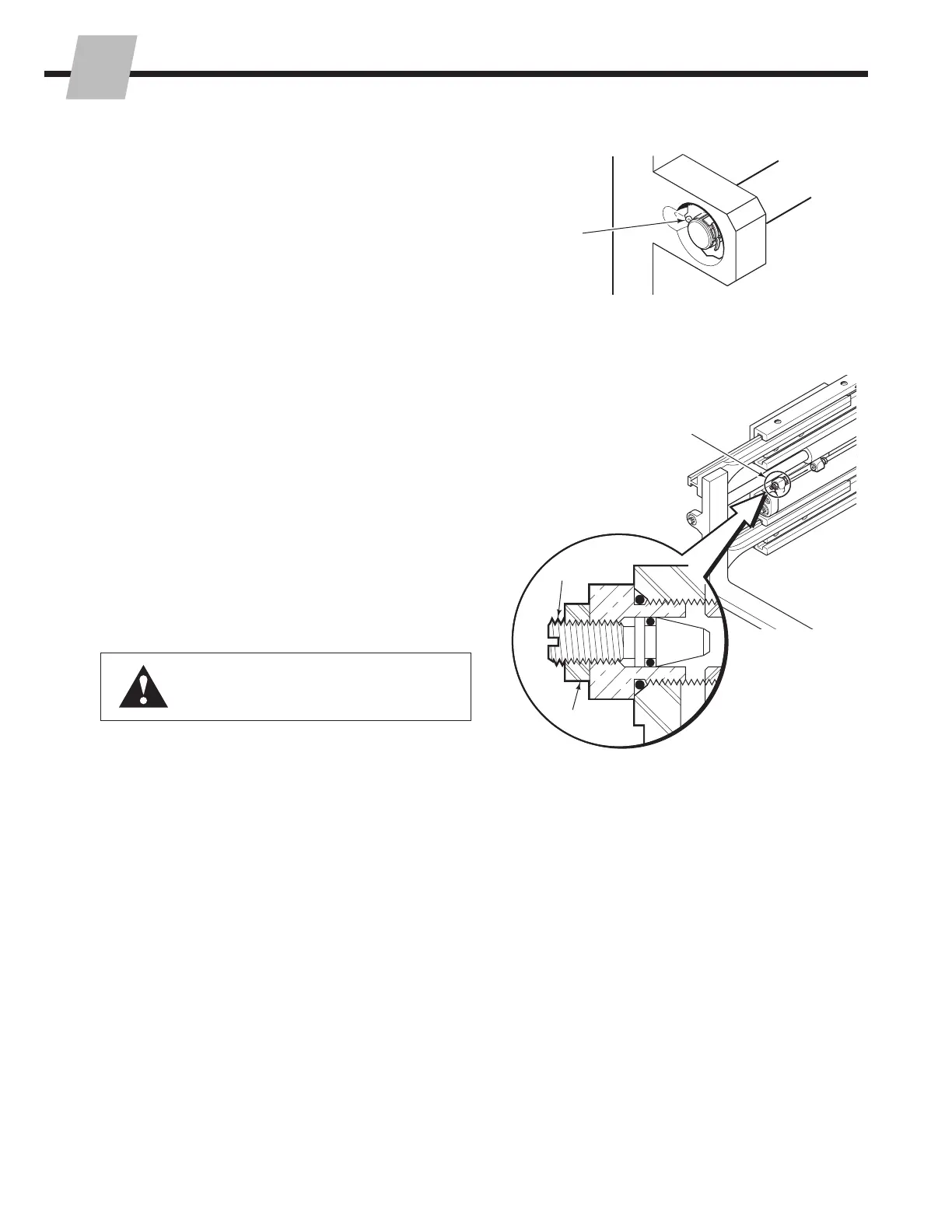
1 Check the cylinder anchor nuts for properly installed
locking caps and cotter pins.
2 Check for external leaks at the fittings and rod ends.
25D, 35D, 40D and 50D Clamps – The clamp utilizes a
regenerative hydraulic circuit in the arm opening mode.
The arms will open at a faster speed than when closing.
This is normal. If required, the regenerative function
can be eliminated. Refer to Section 5.6-5.
3 Check for equal arm travel. If arm travel is unequal, the
restrictor cartridges should be adjusted as follows:
A Loosen the jam nuts on the restrictor cartridges.
Screw in the plungers until they bottom. Screw each
plunger out three full turns.
B Activate the arms to the fully open position
C Activate the arms to close until one arm bottoms
out. Measure the amount of stroke remaining in the
opposite arm.
D If unequal closing movement exceeds 2 in. (50 mm),
screw the plunger in 1/2 turn on the cylinder that
bottoms first.
E Repeat step A through D until unequal closing
movement is less than 2 in. (50 mm).
4 Before picking up a load, cycle the clamp function
through several full cycles. Check for operation in
accordance with ITA (ISO) standards.
WARNING: Make sure all personnel are
clear of the clamp during testing.
CL0459.eps
CL0491.eps
1
3
Check for properly
installed locking
caps and cotter pins
Restrictor Cartridge
Plunger
Jam Nut
NSTALLATION
I

Table of Contents

Questions and Answers:

Cascade 70D Specifications

General IconGeneral
BrandCascade
Model70D
CategoryPower Tool
LanguageEnglish

Summary

INTRODUCTION, Section 1

1.1 Introduction

Provides installation, maintenance, troubleshooting, service, and specifications for D-Series clamps.

1.2 Special Definitions

Explains WARNING, CAUTION, IMPORTANT, and NOTE statements used throughout the manual.

INSTALLATION, Section 2

2.1 Truck Requirements

Details truck relief setting, flow volume, and carriage mount dimensions for compatibility.

2.2 Recommended Hydraulic Supply

Specifies hose and fitting requirements for non-sideshifting and sideshifting clamp hydraulic supply.

2.3 Installation Procedure

Step-by-step guide for attaching the overhead hoist, preparing hoses, mounting the attachment, and securing hooks.

2.4 Custom Arm Installation

Instructions for fabricating and installing custom arms on attachment bases.

2.5 Prior to Operation

Pre-operation checks including cylinder nuts, leaks, arm travel, and functional testing.

PERIODIC MAINTENANCE, Section 3

3.1 100-Hour Maintenance

Maintenance tasks for every 100 hours: anchor joint, arm bearings, and capscrew torque.

3.2 500-Hour Maintenance

Maintenance tasks for every 500 hours: hook clearance, lower/upper capscrews, and clamp force.

3.3 1000-Hour Maintenance

Inspect arm bearings for wear; replace if worn below 0.040 in. thickness.

3.4 2000-Hour Maintenance

Inspect arm bearings for wear and tighten frame mounting plate capscrews.

TROUBLESHOOTING, Section 4

4.1 General Procedures

Covers truck system requirements, tools, and a general troubleshooting chart for common issues.

4.2 Plumbing – Top Mount Valve

Hosing diagrams and circuit schematics for non-sideshifting units with top mount valves.

4.3 Plumbing – Center Mount Valve

Hosing diagrams and circuit schematics for non-sideshifting units with center mount valves.

4.4 Attachment Troubleshooting

Lists potential problem areas for clamp function, including pressure tests and electrical checks.

SERVICE, Section 5

5.1 Attachment Removal

Step-by-step guide to safely remove the attachment from the lift truck.

5.2 Arms

Procedures for arm assembly removal, installation, inspection, and service.

5.3 Cylinders

Procedures for hydraulic cylinder removal, installation, and service.

5.4 Cylinder Service

Procedures for cylinder disassembly, inspection, and reassembly.

5.5 Restrictor Cartridges

Information on restrictor cartridges, including adjustment and service.

5.6 Check Valves

Procedures for removing and servicing check valves in top and center mount assemblies.

5.7 Base Unit

Procedures for disassembling and reassembling the base unit frame and mounting plate.

5.8 Solenoid Valve

Procedures for solenoid valve coil service and general valve service.

SPECIFICATIONS, Section 6

6.1 Specifications

Provides technical specifications for the D-Series clamps, including hydraulics and carriage.

Related product manuals