— 5 —
Button Matrix
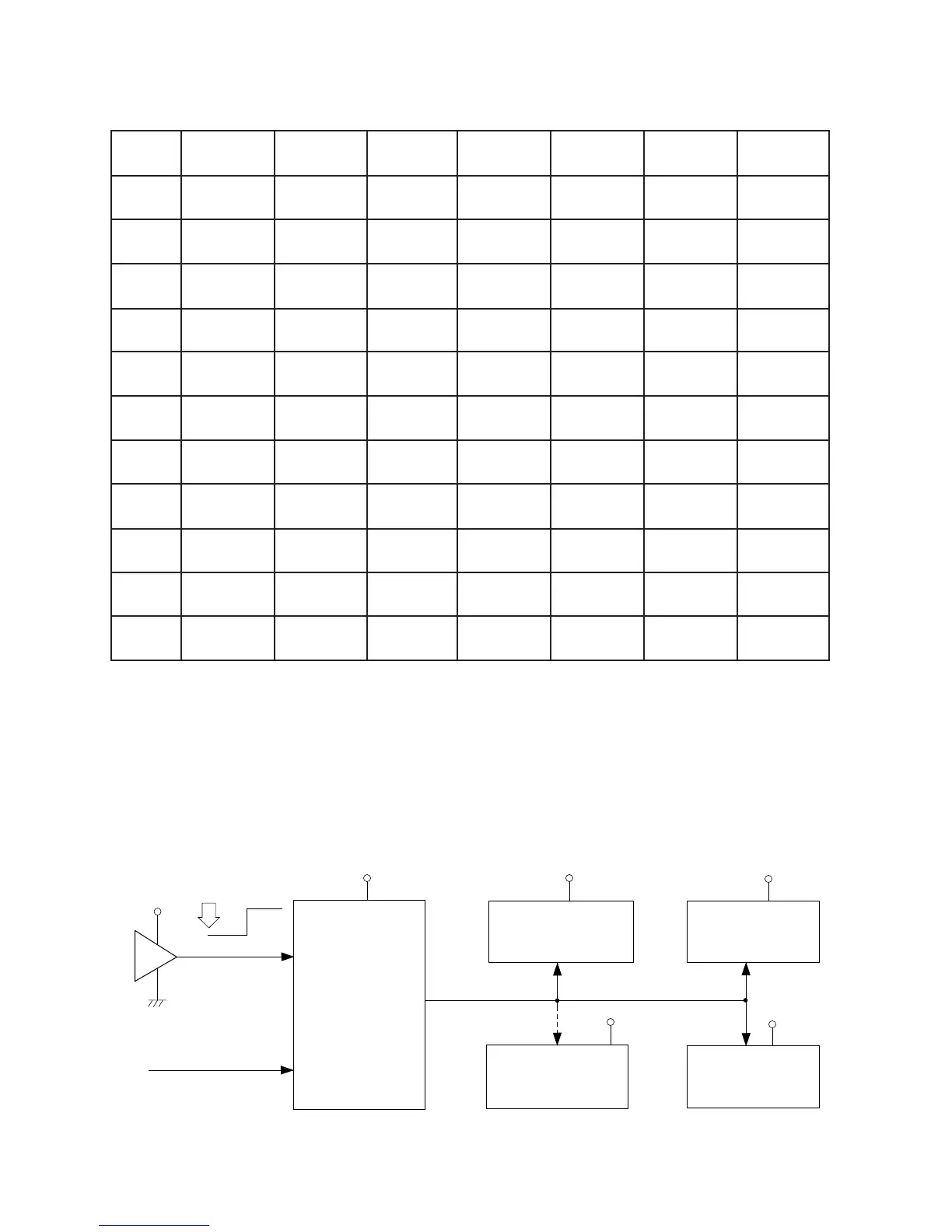
Reset Circuit
Initial reset
When batteries are set or an AC adapter is connected, the reset IC provides a low pulse to the CPU.
The CPU then initializes its internal circuit and clears the working strage RAM.
Power ON reset
When the power switch is pressed, the CPU receives a low pulse of POWER signal. The CPU provides
APO signal to the power supply circuit, then provides RESET signal to the DSP, the key touch LSI and
the KO signal generators.
VDD
Battery set
RESET
CPU
LSI102
HD6433298A36P
Reset IC
IC104
RE5VA35AA
Working Strage RAM
LSI104
SRM2264LC90,10
DSP
LSI105
HG51B155FD
Key Touch LSI
LSI106
HG52E35
DVDD
DVDD
DVDD
VDD
VDD
-RESET
POWER
From power switch
KO Signal Generator
IC303/304
TC74HC174P
-NMI
KI1 KI2 KI3 KI4 KI5 KI6 KI7
KO0 Registration 3 2 1 0
KO1 Control Demo Layer Split
KO2 Tone Rhythm 9 8 7 +
KO3 Accomp 6 5 4 -
KO4 G# down A down A# down B down G down
KO5 ScaleMode ScaleTune B up A# up A up G# up G up
KO6 Intro Start/Stop
KO7 C up C# up D up D# up E up F up F# up
KO8 C down C# down D down D# down E down F down F# down
KO9 Mode Pad B Pad D Pad A Pad C
KO10 Rec
Song
Memory
Touch
Response
Transpose/
Tune
Magical
Preset
Digital
Effect
Tempo
Down
Tempo
Up
Synchro/
Ending
Variation/
Fill-In
Normal/
Fill-In
Scale
Memory 1
Scale
Memory 2
Scale
Memory 3
Scale
Memory 4
 Loading...