6.
DIGITAL
CIRCUIT
BLOCK
DIAGRAM
j*027C266CaOA1M
I33K
MP044S4C-15L
t
ViH
n
J*O7tl0H
1
r
Su^CWJ
4#O7lt0H
j*02X121CC43«
MSKbyia)
tub
RAM
(I)
j*04464C*1SL-1
(•Kbyul
ChJ*
>Urf«M
LSI
MM7H17S
write*
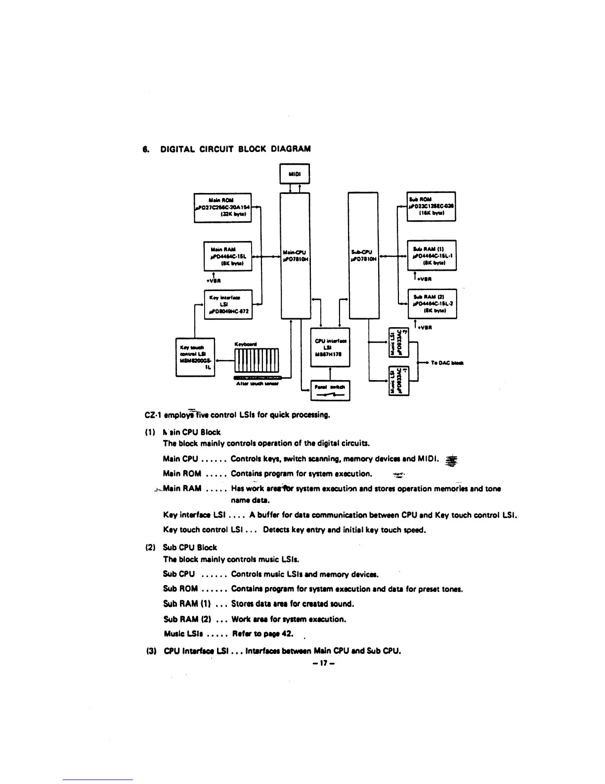
CZ-1
employtiive
control LSIt
for
quick processing.
(1)
K
lin
CPU
Block
The block
mainly
controls
operation of the digital circuits.
Main
CPU
Controls
keys,
switch scanning, memory devices and
MIDI,
ap
Main
ROM
Contains program for
system execution.
_
^Main RAM Has work aresrfbr
system
execution and stores operation memories and tone
name
data.
Key interface
LSI
...
.
A
buffer for
data
communication
between
CPU
and Key touch control LSI.
Key touch control LSI . .
.
Detects
key entry
and initial key touch
speed.
(2)
Sub CPU Block
The block
mainly controls music
LSts.
Sub CPU
Controls
music
LSIs
and memory
devices.
Sub ROM Contains program
for
system
execution
and
data for preset
tones.
Sub
RAM
(1)
...
Stores data area
for
created sound.
Sub
RAM
(2)
...
Work area
for system execution.
Music LSIs
Refer to page 42.
(3)
CPU
Interface LSI
. .
.
Interfaces
between
Main
CPU
and
Sub CPU.
-17-
 Loading...