— 8 —
POWER SUPPLY CIRCUIT
The power supply circuit generates seven voltages as shown in the following table. VDD voltage is always
generated. The others are controlled by APO signal from the CPU.
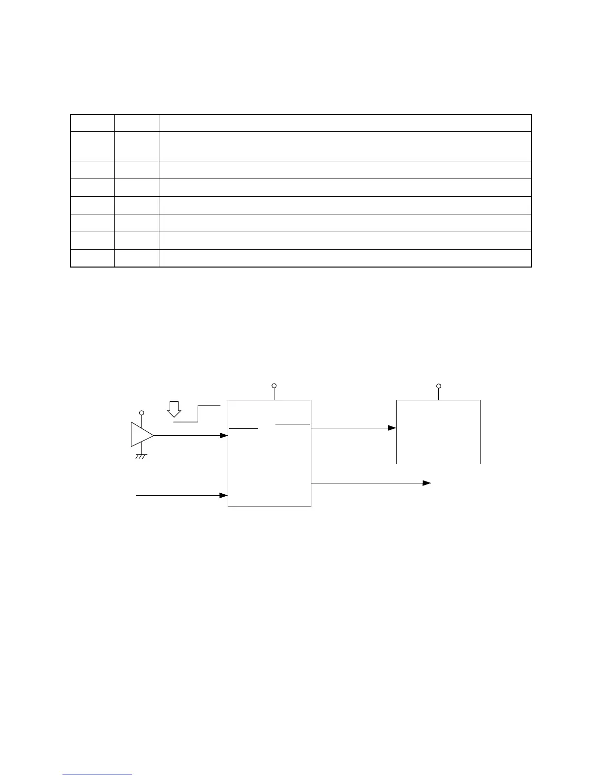
RESET CIRCUIT
When batteries are set or an AC adapter is connected, the reset IC provides a low pulse to the CPU. The
CPU then initializes its internal circuit, and clears the working storage RAM.
When the power switch is pressed, the CPU receives a low pulse of POWER signal. The CPU sends APO
signal to the power supply circuit, also sends a reset signal to the DSP.
Reset IC
IC15
RN5VD40AA
DSP
LSI2
UPD914GM-3ED
VDD
Reset signal
To power supply circuit
VDD
Battery set
RESET
VDD
POWER
From power switch
NMI
RESET
RESETB
APO
SYSRST
CPU
LSI15
UPD703025AGC33
SCK1
Name Voltage (Manily) For operation of
VDD +5.2V
CPU, Reset IC, DSP, Sound source ROM, Working storage RAM, Effect RAM,
LED driver
DVD +5V CPU, Sustain jack, MIDI jack
CVD +5V DAC, Filter
FVD +5V FDD Unit
AVCC 13.4V Power amplifier
VEE +25V LCD driver
VDA +5V Console PCB
 Loading...