HELPLINE NO 08448012949
11
ORIGINAL INSTRUCTIONS
6. GUARD ADJUSTMENT (See Fig. D)
Before any work on the machine itself, pull
the mains plug.
For work with grinding or cutting discs, the
wheel guard must be mounted.
Wheel Guard for Grinding
Turn off and unplug the tool. Never operate
grinder without guard in place. Adjust the guard
to protect your hands and to direct grind debris.
Loosen the Clamping Lever. Position the guard
at the required angle. Then tighten the Clamping
Lever.
To move the guard you must release the
Clamping Lever (10). The guard can then be
rotated to provide maximum protection against
sparks and debris. Finally, tighten the Clamping
Lever until it touches the gear case.
NOTE: with the Clamping Lever open the Clamp
Adjusting Nut (9) can be adjusted to ensure the
guard is securely clamped after the Clamping
Lever is nally closed.
Wheel Guard for Cutting
WARNING! For cutting metal, always work
with the wheel guard for cutting (9).
The wheel guard for cutting (9) is mounted in the
same manner as the wheel guard for grinding (3).
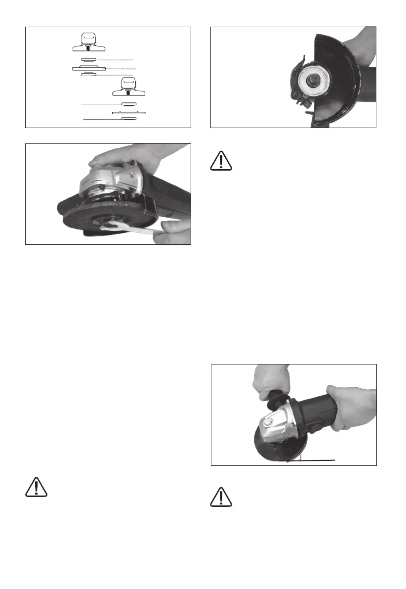
7. TO USE THE GRINDER (See Fig.E)
ATTENTION: Do not switch the grinder
on whilst the disc is in contact with the
workpiece. Allow the disc to reach full speed
before starting to grind.
Hold your angle grinder with one hand on the
main handle and other hand rmly around the
auxiliary handle.
Always position the guard so that as much of the
exposed disc as possible is pointing away from
you.
Be prepared for a stream of sparks when the disc
touches the metal.
For best tool control, material removal and
minimum overloading, maintain an angle between
the disc and work surface of approximately 15
o
-30
o
when grinding.
Use caution when working into corners as contact
with the intersecting surface may cause the
grinder to jump or twist.
When grinding is complete allow the workpiece to
cool. Do not touch the hot surface.
8. CUTTING
WARNING! For cutting metal, always work
with the wheel guard for cutting.
When cutting, do not press, tilt or oscillate the
machine. Work with moderate feed, adapted to
the material being cut.
8
4
7
8
4
7
Fig. A
Fig.B
Fig. C1
Fig. C2
Fig. C3
Fig. D
Fig. E
15
o
-30
o
8
4
7
8
4
7
Fig. A
Fig.B
Fig. C1
Fig. C2
Fig. C3
Fig. D
Fig. E
15
o
-30
o
8
4
7
8
4
7
Fig. A
Fig.B
Fig. C1
Fig. C2
Fig. C3
Fig. D
Fig. E
15
o
-30
o
 Loading...