Do you have a question about the Challenger Lifts CL4P7 and is the answer not in the manual?
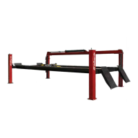
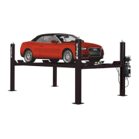
This document outlines the installation, operation, and maintenance procedures for the CL Challenger Lifts, specifically models CL4P9S, CL4P9X, and CL4P9W, which are four-post, surface-mounted lifts with a 9,000 lb capacity.
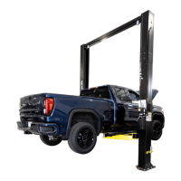
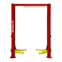
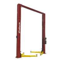
The CL Challenger Lifts are designed to raise vehicles for maintenance and storage purposes in a service bay. These lifts are surface-mounted, meaning they are installed directly on a concrete floor without requiring extensive excavation. The core function involves a hydraulic system that elevates two runways, which support the vehicle's wheels, to a desired working height. A mechanical locking system ensures the vehicle remains securely elevated at various positions. The lift is operated via a power unit, which can be configured for either 115V or 230V single-phase electrical supply. The design incorporates four columns, two runways (one power runway and one idler runway), cross beams, and a cable system that synchronizes the lifting action across all four posts. Safety features, such as lock pawls and slack cable latches, are integrated to prevent accidental lowering and ensure stability.
Installation and Setup: The installation process begins with a thorough site assessment, including checking vertical clearance and ensuring the concrete floor meets minimum depth, strength (3500 psi), and curing requirements. The floor should be level within 1/2 inch side-to-side and 2 1/2 inches front-to-rear. Anchor bolts, if used, must be installed at least 8 inches from any cracks or expansion joints. Electrical requirements specify a dedicated circuit with a single-pole (115V) or double-pole (230V) circuit breaker or time delay fuse, sized for the lift's full load amperage (15 amps for 115V, 18 amps for 230V).
The physical assembly involves positioning the columns, runways, and cross beams according to the layout diagram. Cables are routed through sheaves and attached to the columns, and the hydraulic cylinder is extended. The mechanical lock release bar is installed, and the lock clevis is checked for secure positioning. The power unit is then installed on one of the columns, and hydraulic lines are connected, ensuring no kinks or twists. After filling the power unit with three gallons of 10wt anti-foam anti-rust hydraulic oil or Dexron III ATF (oils with detergents are explicitly prohibited), the system is bled by raising and lowering the lift several times. Final adjustments include leveling the runways and cross beams, synchronizing the cables, and tightening all fasteners. Safety decals, including caution, warning, and safety instructions, must be correctly placed on the power unit and columns.
Operating the Lift: To operate the lift, entrance ramps are placed in the slotted holes at the front of the runways, and the vehicle is driven onto the lift. The parking brake should be set, and the entrance ramps removed before lifting. Removable wheel stops are then installed at the front of both runways. To raise the vehicle, the power pack button is pressed. Once the desired working height is reached, the button is released, and the lift is lowered slightly until the safety locks engage. It is crucial to verify that all locks are properly engaged and the vehicle is level before working underneath.
Lowering the Lift: Before lowering, the area under the vehicle must be clear of personnel and tools. The vehicle is first raised slightly to disengage the locks. The mechanical lock handle is then rotated clockwise and held to keep the locks disengaged while the lowering valve handle is depressed. It is important to observe the lift as it lowers to ensure it descends evenly. If it does not, the lift should be raised again, and the locks re-checked for proper disengagement. The lift should be fully lowered until the crossbeams rest against the base plate to release hydraulic pressure from the system.
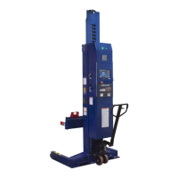
Optional Accessories: Several optional accessories enhance the functionality of the CL Challenger Lifts:
Proper maintenance and inspection are critical for safe operation and extended service life of the CL Challenger Lifts. The manual emphasizes that only qualified personnel should perform maintenance, following lockout/tagout instructions per ANSI Z244.1.
Daily Maintenance:
Weekly Maintenance:
Monthly Maintenance:
Important Maintenance Notes:
The owner/employer is responsible for ensuring that lift operators are qualified and trained, maintaining periodic inspection and maintenance records, and displaying operating instructions and safety manuals in a conspicuous location. The manual also highlights the importance of using only certified attachments, accessories, or modifying components to avoid nullifying the lift's certification.
| Number of Lifts | 1 |
|---|---|
| Weight | 1, 900 lbs |
| Lifting Height | 82 inches |
| Overall Height | 145 inches |
| Outside Column to Column | 114 inches |
| Max Lift Height | 82 inches |
| Inside Column to Column | 102 inches |