The Protector System is designed to increase the safety
and functionality of your garage door motor.
The system uses an invisible beam across the garage
door opening. If an obstruction breaks the light beam
while the door is closing, the door will stop and reverse
to full open position.
NOTE: The brackets must be connected and fastened so
that the sending and receiving eyes face each other.
The brackets must be securely fastened to a solid surface
such as the studs on either side of the door, or add a piece
of wood at each location if installing in masonry
construction.
The invisible light beam path must be unobstructed.
Ensure no part of the door (or door tracks, springs, hinges,
rollers or other hardware) interrupts the beam while the
door is closing. If it does, add a piece of wood to build out
each sensor mounting location to the minimum depth
required for light beam clearance.
Assembly Process:
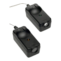
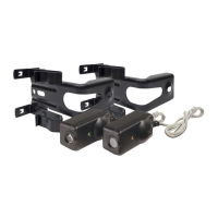
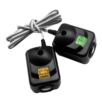
The IR Beams are supplied preassembled, complete with
two sensors, wiring and wall brackets (fig 2 & fig 3).
Install the mounting brackets and sensors to either side of
the inside of the garage door, and at a height of no greater
than 100 mm off the garage floor.
The brackets are designed to be used for Wall or Floor
fixing with a variety of hole combinations to achieve the
desired results.
Drill the required holes and install the brackets with wall
plugs and screws provided. Ensure they do not obstruct
the door movement.
Wiring Process:
Align the Sensors to face each other and tighten if
necessary. The wiring should exit from the bottom of the
housing to maintain the correct IP rating and continued
operation.
One sensor is a Sending Eye, the other is a Receiving
Eye. Try to avoid positioning these indirect sunlight as this
may interfere with the operation of the beams.
Run both sets of wires back to the power head CONTROL
PANEL. Ensure the wires are well supported and do not
interfere or get damaged by movement of the door panels
or spring hardware.
At the Power head end, cut the wires to the correct length
and strip each wire back around 15 mm.
Twist both White wires together and install into “quick
release” terminal (white).
Twist both Black wires together and install into“quick
release” Terminal (Grey).
For Specific Connections for each product, refer to the
following pages, or to your Product Handbook.
Activation:
After the Protector System has been connected to the
powerhead, the system will be automatically activated.
To protect small children, install the Protector System
no higher than (100 mm) above the floor.
For Commercial door an additional beam is required
at 650 mm.
Disconnect power to the door opener before installing
the Protector System.
™
™
The Protector System
Safety Reversing Sensor
Model 774ANZ
Model 774AML
™
Review all safety warnings outlined in your Garage
door operator owner’s manual. Ensure that the door
and all its fixtures and fittings are in good condition.
Red LED
MUST BE ON
R ed LE D
MUS T B E ON
S afety R eve rsing S ens or
6" (15 cm) max. above floor
For Commercial doors
Safety Reversing Sensor
650 mm and 100 mm
For Residential Doors
Safety Reversing Sensor
650 mm
100 mm
0 mm (Floor)
For Commercial doors ensure the door works well in manual operation.
Commercial Door / Residential Door
M6 FLANGE
NUT
774 IR
BEAM
2 CORE WIRE
CABLE
WALL
BRACKET
PLASTIC WALL
PLUG
WALL
SCREW
M6 COACH
SCREW
Figure 2
Figure 3
Figure 1
View 1
View 2