27
C9
2
J2
21
4
2
2
4
7
6
5
4
R2
1
1
1
9
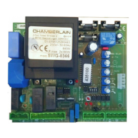
LEARN
1 2 3 4 5 6 7
LMEP1 LMEP2
INTRLK
COM
STOP CLOSE OPEN
STOP CLOSE OPEN
AUX ANT
Auxiliary
Antenna
Connection
Purple Wire Antenna
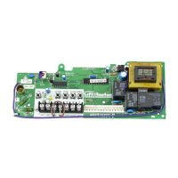
Diagnostic LED Field Wiring Terminal Factory Wiring Connector
Timer to Close
Button
Learn
Button
Stop
Button
Close
Button
Open
Button
APPLICATION
Available to all limited duty commercial door operators using the
logic control board. Example model identifier: MT-5011-E.
NOTE: A monitored safety device MUST be installed for B2 wiring
mode.
1
INSTALLATION
1. Disconnect power to operator.
2. Remove all wires from the existing logic board:
• Unplug Factory Wiring Connector (P1).
• Field control wiring from terminal strip.
NOTE: Remember location of all wiring connections for
reinstallation.
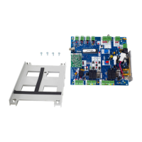
3. Remove the logic board from the mounting posts (5).
4. Install the new logic board into the operator, making sure that
the logic board is correctly oriented. Press firmly until all of
the mounting posts are completely through the mounting
holes and secure the board with the plastic nuts (2).
5. Plug factory wiring connector into P1 connector on logic
board.
6. Reconnect all field wiring to the field wiring terminal strip.
7. Make sure the electrical box is clear of all debris and tools.
8. Reconnect power to the operator and verify operation. Refer to
page 2 to reprogram remote controls and settings as
necessary.
LOGIC CONTROL BOARD
LOGIC BOARD
REPLACEMENT KIT
K1A6424-2 (315MHZ)
& K1A6424-3 (390MHZ)
To avoid SERIOUS personal INJURY or DEATH from
electrocution, DISCONNECT electrical power to operator
BEFORE proceeding.
WARNING: This product can expose you to chemicals
including lead, which are known to the State of California to
cause cancer or birth defects or other reproductive harm.
For more information go to www.P65Warnings.ca.gov