EasyManuals Logo
Home>Chenbro>Chassis>SR30169 Plus

Chenbro SR30169 Plus User Manual

Default Icon
20 pages
To Next Page IconTo Next Page
To Previous Page IconTo Previous Page
Page #16 background imageLoading...
Page #16 background image
4-port 12Gb/s SAS/ SATA Backplane - 80H10230101A0 User Manual
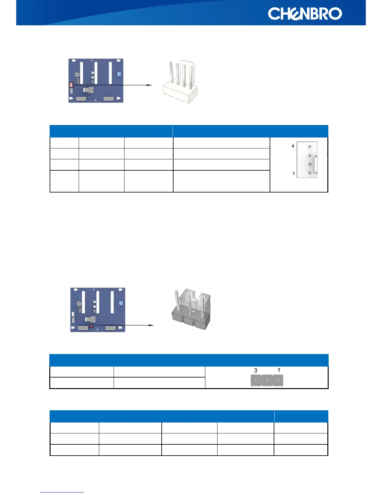
Table 6. 4-pin Fan Header
3.4 HDD Access Mode Jumper (JP01)
This jumper allows you to configure HDD access LED and fail LED in two modes. The setting
“HDD access mode” enables that a 3.5” SATA HDD controls the activity LED through the pin 11 of
its SATA power connector. While the setting “SGPIO decode mode” is different, the HDD activity
LED is controlled by side-band SGPIO signals which also support HDD failure, indicated by a solid
red LED for each drive.
Jumper setting
Descriptions
Picture
1-2
HDD access mode
2-3(default)
SGPIO decode mode
Table 7.HDD Access Mode Jumper
Pin No.
Signal Name
Input/output
Signal Name
Picture
1
GND
GND
Power GND
2
V12
PWR
Power +12V
3
Fan_tach
I
FAN Sensor Tachometer
4
Fan_PWM
O
FAN PWM signal to control fan
speed
HDD Status
Blue LED
Green LED
Red
Access Mode
R/W Activity
On
On
N/A
Pin 11 control
Idle
On
Off
Off
Fail
On
Off
On
SGPIO

Questions and Answers:

Question and Answer IconNeed help?

Do you have a question about the Chenbro SR30169 Plus and is the answer not in the manual?

Chenbro SR30169 Plus Specifications

General IconGeneral
BrandChenbro
ModelSR30169 Plus
CategoryChassis
LanguageEnglish

Related product manuals