15
Console, Auxiliary, and USB Port Connections
The connections described in Table 2 provide system management access.
Note The USB port (version 1.1) is intended for future use only.
Power Connections
Connect the router power cord to a 15A, 120 VAC power source or 10A, 240 VAC power source.
Warning
This product relies on the building’s installation for short-circuit (overcurrent) protection. Ensure that the
protective device is rated not greater than: 15A, 120VAC (10A, 240VAC). Statement 1005
Note The input voltage tolerance limits for AC power are 85 and 264 VAC.
6 Power Up the Router
Checklist for Power Up
You are ready to power up the Cisco 1841 router after the following steps are completed:
• Chassis is securely mounted and grounded. (See the “Install Chassis” section on page 4.)
• Power and interface cables are connected. (See the “Connecting Cables” section on page 13.)
• Make sure that the external CompactFlash memory card is properly seated into the slot. For installation instructions, refer
to the online Cisco 1800 series hardware installation documentation at the following URL:
http://www.cisco.com/univercd/cc/td/doc/product/access/acs_mod/1800/hw/index.htm
• PC with terminal emulation program is connected to the console port, powered up, and configured for 9600 baud, 8 data
bits, 1 stop bit, no flow control, and no parity.
• Suitable PC COM port is selected in the terminal emulation program.
Note For initial power up, a direct console connection is recommended. After the initial configuration is completed, a remote
modem connection can be used for router management.
Caution To ensure adequate cooling, never operate the router unless the cover and all modules and cover plates are installed.
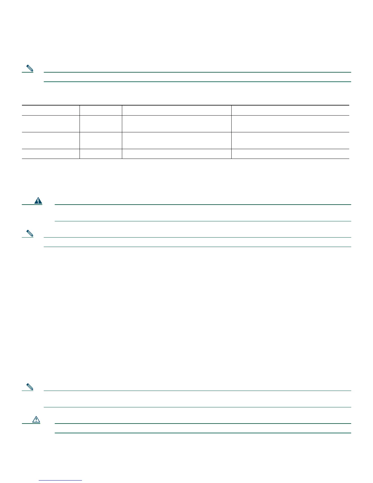
Table 2 Console and Auxiliary Port Connections
Port or Connection Color or Type Connected To: Cable
Console Light blue PC or ASCII terminal communication
port (usually labeled COM)
RJ-45-to-DB-9 console cable
Auxiliary Black Modem for remote access RJ-45-to-DB-9 console cable and
DB-9-to-DB-25 adapter
USB — Peripheral devices USB cable
 Loading...