1-6
Cisco 2900 Series and 3900 Series Hardware Installation Guide
OL-18712-02
Chapter 1 Overview of the Routers
Chassis Views
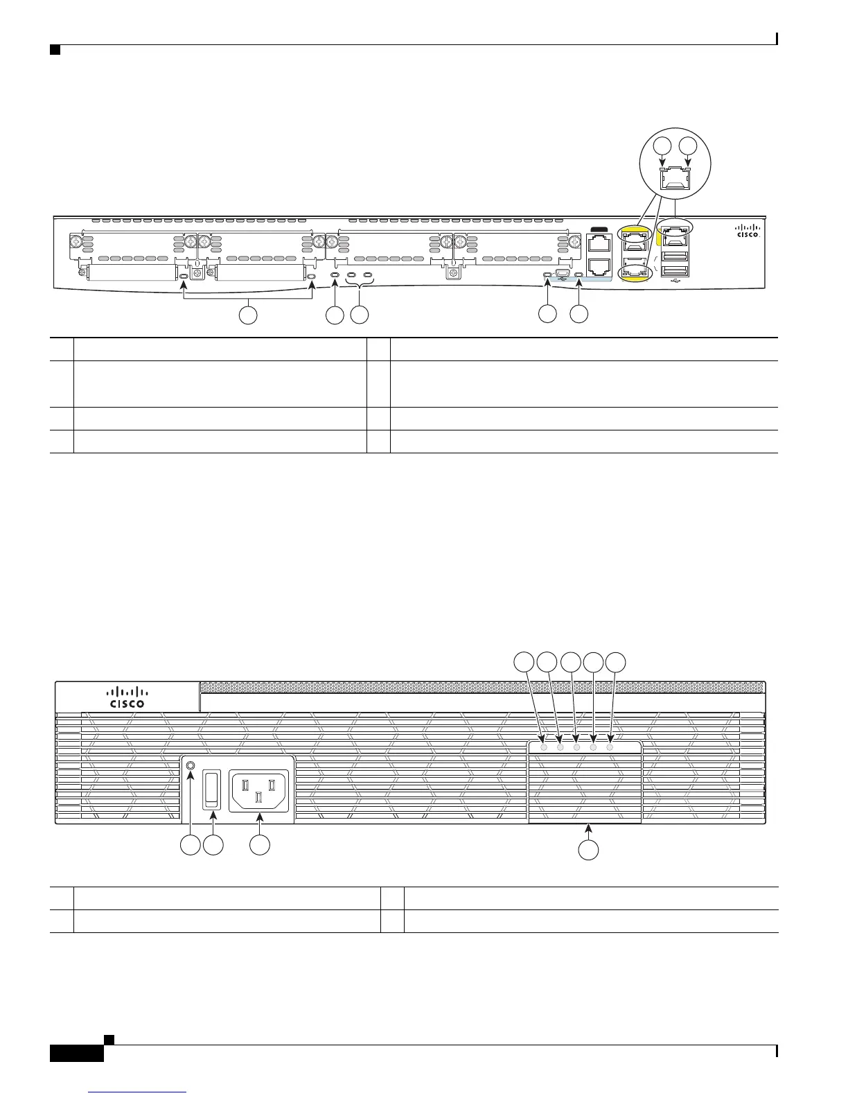
Figure 1-6 Back Panel LEDs of the Cisco 2911 Router
Cisco 2921 and Cisco 2951 Chassis
Figure 1-7 on page 1-6— Front panel
Figure 1-8 on page 1-7— Back panel
Figure 1-9 on page 1-8— Back panel LEDs
Figure 1-7 Front Panel of the Cisco 2921 and 2951 Routers
1 CompactFlash 0 and 1 (0, Far right) 2 ISM
1
1. Integrated Service Module (ISM)
3 PVDM3
PVDM 0, 1, (0, Far right LED)
4 EN (Enable USB console)
5 EN (Enable RJ-45 console) 6 S (Speed)
7 L (Link)
ISM
EN
EN
S
L
S
L
USB
1
0
CONSOLE
AUX
GE 0/1
GE 0/2
G
E
0
/
0
250990
2
4
5
6 7
1
EHWIC 3
EHWIC 2 EHWIC 1 EHWIC 0
CF 0
CF 1
PVDM1 PVDM0
3
2911
DO NOT REMOVE DURING
NETWORKING OPERATION
DO NOT REMOVE DURING
NETWORKING OPERATION
1 AC OK
1
2 Power On/off switch
3 AC power connector 4 Optional RPS adapter (Blank panel shown)
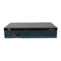
Cisco 2900 Series
SYS ACT
POE RPS
PS
250899
1
5
6
7
9
8
4
2 3
 Loading...