16 Upgrading Cisco 4500, Cisco 4500-M, Cisco 4700, and Cisco 4700-M Memory
Memory Replacement Procedures
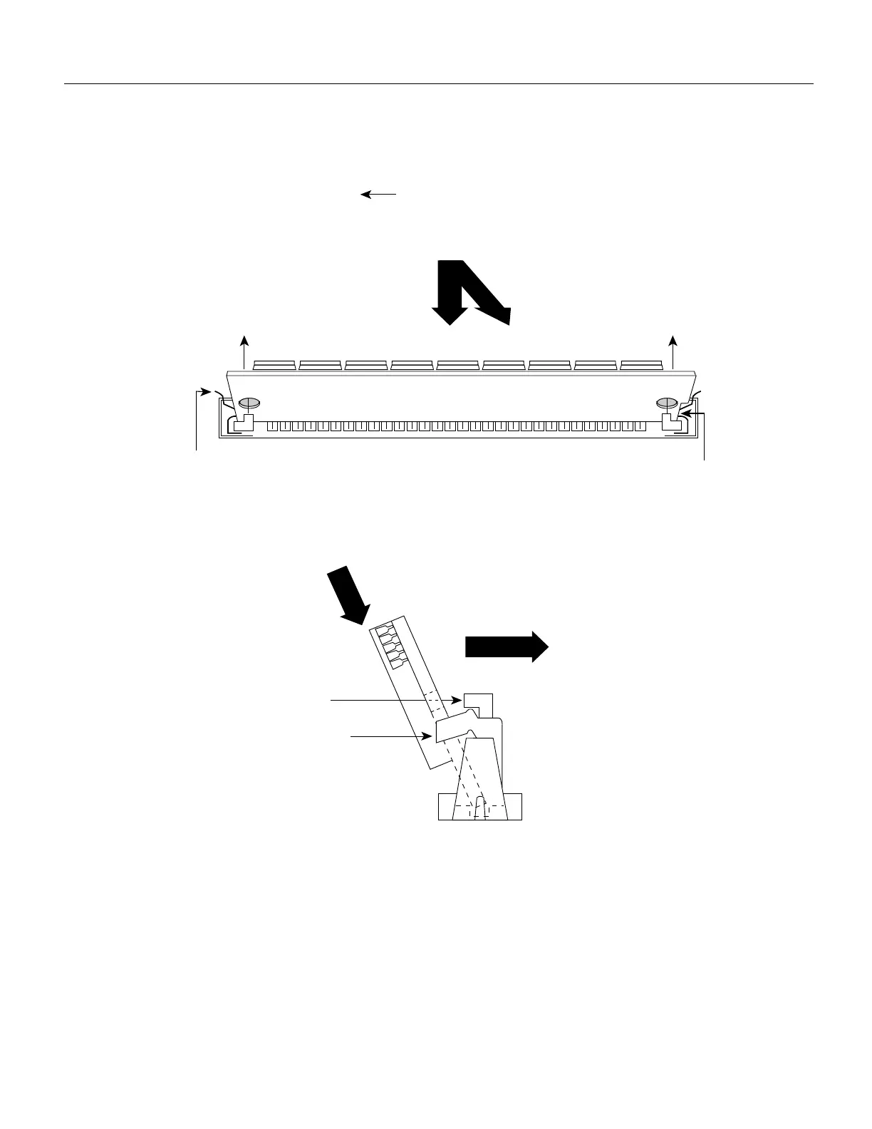
Figure 12 Installing Main Memory SIMMs
Removing and Replacing Shared Memory SIMMs
Take the following steps to replace the shared memory SIMMs:
Step 1 Unplug the chassis power cord and network connections.
Step 2 Attach an ESD-preventive wrist strap and ensure that it makes good contact with your skin.
Connect the equipment end of the wrist strap to the metal back plate of the chassis, avoiding
contact with the connectors.
Step 3 Remove the chassis cover as described in the section “Accessing the Internal Components
of the Router” on page 5.
2. Push the SIMM down and back.
1. Insert the SIMM into the socket at an angle 45° from vertical.
The socket guide posts insert
through the SIMM holes
(on both sides).
3.
The locking spring will
clip the back of the SIMM
when it is fully installed
(on both sides).
4.
H1152
Top view
Front of the chassis
Polarization
notch
1. Insert the SIMM into the socket at an angle 45° from vertical.
The socket guide posts insert
through the SIMM holes
(on both sides).
3.
The locking spring will
clip the back of the SIMM
when it is fully installed
(on both sides).
4.
Side view
2. Push the SIMM down and back.
 Loading...


