6-51
Hardware Installation Guide for Cisco 4000 Series Integrated Services Routers
OL-32185-02
Chapter 6 Install and Upgrade Internal Modules and FRUs
Remove and Replace Cisco 4000 Series ISRs Power Supplies
Step 2 Ensure that the power switch is in the Standby position.
Step 3 Remove the plastic cover from the terminal block. Save the covers for reinstallation after you finish
wiring. See Figure 6-32.
Step 4 Use a screwdriver to loosen the terminal block captive screws, as shown in Figure 6-36.
Step 5 Repeat these steps for the remaining DC input power source wire as applicable.
Step 6 Remove the input power cable from the terminal block, and gently push it out of the terminal block.
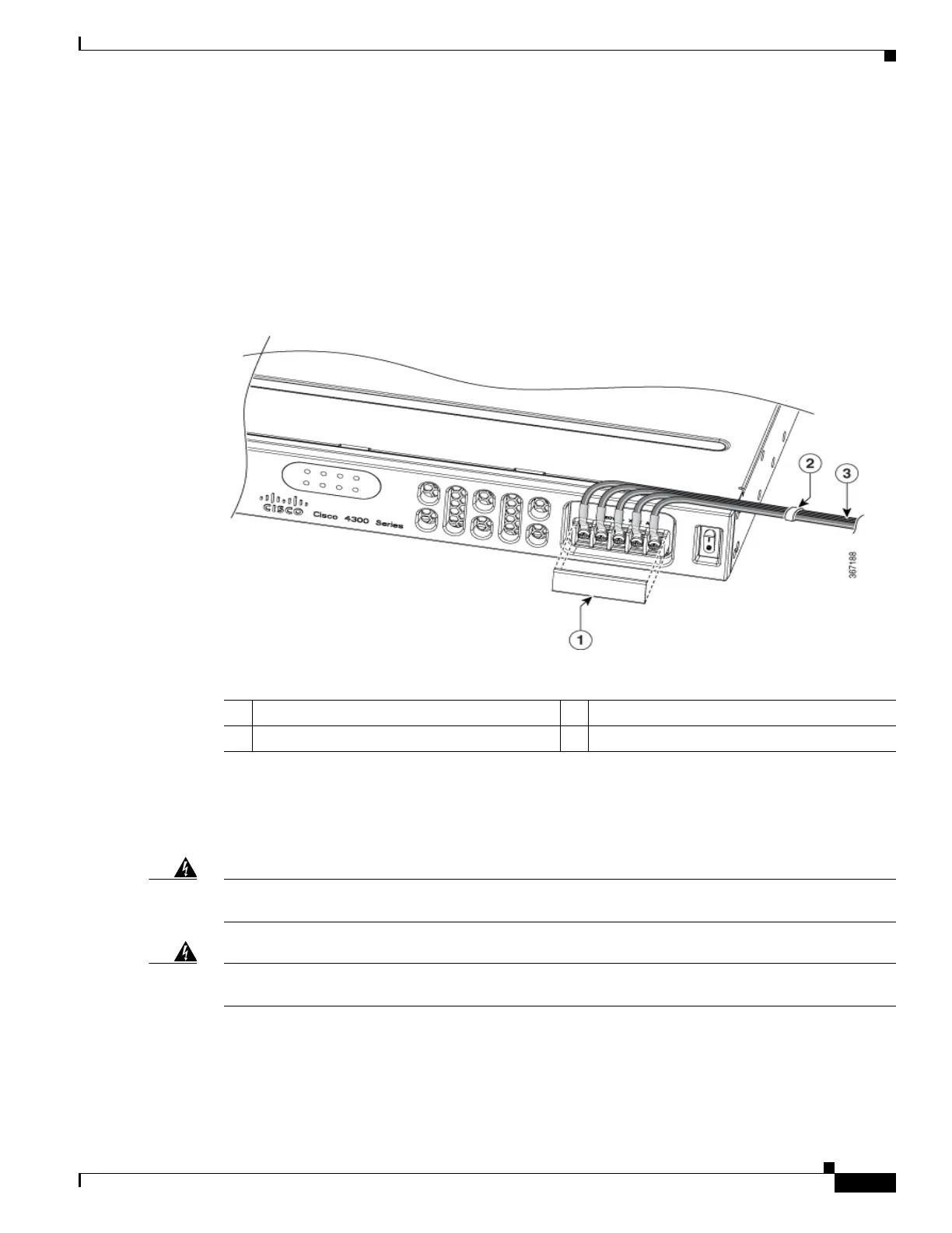
Figure 6-37 Remove the Plastic Cover and DC Input Power
Install DC Input Power on Cisco 4331 ISR
Warning
Before performing any of the following procedures, ensure that power is removed from the DC
circuit.
Statement 1003
Warning
Only trained and qualified personnel should be allowed to install, replace, or service
this equipment.
Statement 1030
This section describes how to install the DC power supply input power leads to the Cisco 4331 Router
DC input power supply.
1 Plastic Cover Cable Tie
DC Power Source

 Loading...