11
Figure 8 Cisco ASR 1002-X Integrated Route Processor Ethernet Management Port Connector
Step 2 Insert the other end of the RJ-45 cable to your management device or network.
Step 3 Configure to a fixed speed through the command-line interface (CLI) commands.
Connect the Shared Port Adapter Cables
The instructions for connecting the cables for the shared port adapters installed in the Cisco ASR 1002-X Router are contained
in the Cisco ASR 1000 Series Aggregation Services Routers SPA and SIP Hardware Installation Guide.
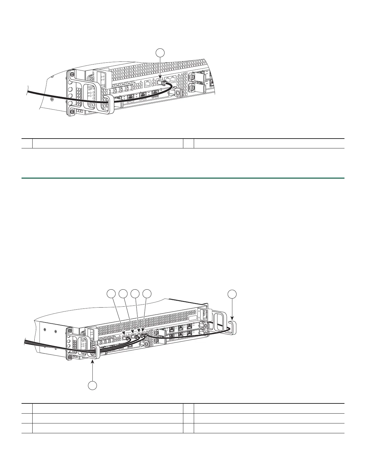
Install the Cables Using the Cable-Management Brackets
Cables coming off the front side of the Cisco ASR 1002-X integrated route processor and SPAs utilize the chassis level
cable-management brackets provided on the chassis rack-mount brackets (see Figure 9).
Figure 9 Cisco ASR 1002-X Integrated Route Processor Cable-Managements
1
MGMT port and cable
1
BITS cable
4
AUX cable
2
MGMT cable
5
Cable-management U feature device
3
CON cable
ASR 1002
stat
pwr
min
maj
cr
it
0
1
C
/
A
A
/
L
0
1
C/
A
A/L
S
TAT
Q
E0
Q
E
1
Q
E
2
Q
E3
B
OOT
CA
R
RI
E
RLI
N
K
P
WR STA
TM
T
S
M
GMT
AU
X
CO
N
S
P
A
-
4X
O
C
3
-
P
O
S
S
T
AT
U
S
0
1
2
3
C
/
A
A
/
L
C
/
A
A
/
L
C/A
A
/
L
C
/
A
A
/
L
A
SR
1
0
0
2
s
ta
t
pw
r
m
i
n
m
aj
c
r
i
t
S
P
A
-
4
X
OC3
-
P
OS
S
TA
T
U
S
0
1
2
3
C
/A
A
/
L
C
/A
A
/L
C
/A
A
/L
C
/A
A
/
L
S
P
A
-
4X
OC3
-
P
OS
S
T
A
T
US
0
1
2
3
C
/A
A
/
L
C
/A
A
/
L
C/A
A
/L
C
/A
A
/L
ST
A
T
Q
E
0
Q
E
1
Q
E
2
Q
E
3
B
O
O
T
CA
RR
I
E
RL
I
N
K
P
W
R
S
T
A
T
M
T
S
M
G
M
TA
UX CO
N
S
P
A
-
4
X
OC3
-
P
OS
S
T
A
T
U
S
0
1
2
3
C
/
A
A
/
L
C/
A
A
/L
C
/A
A
/
L
C/A
A
/L
280287
5
5
1 2 3 4

 Loading...


