42
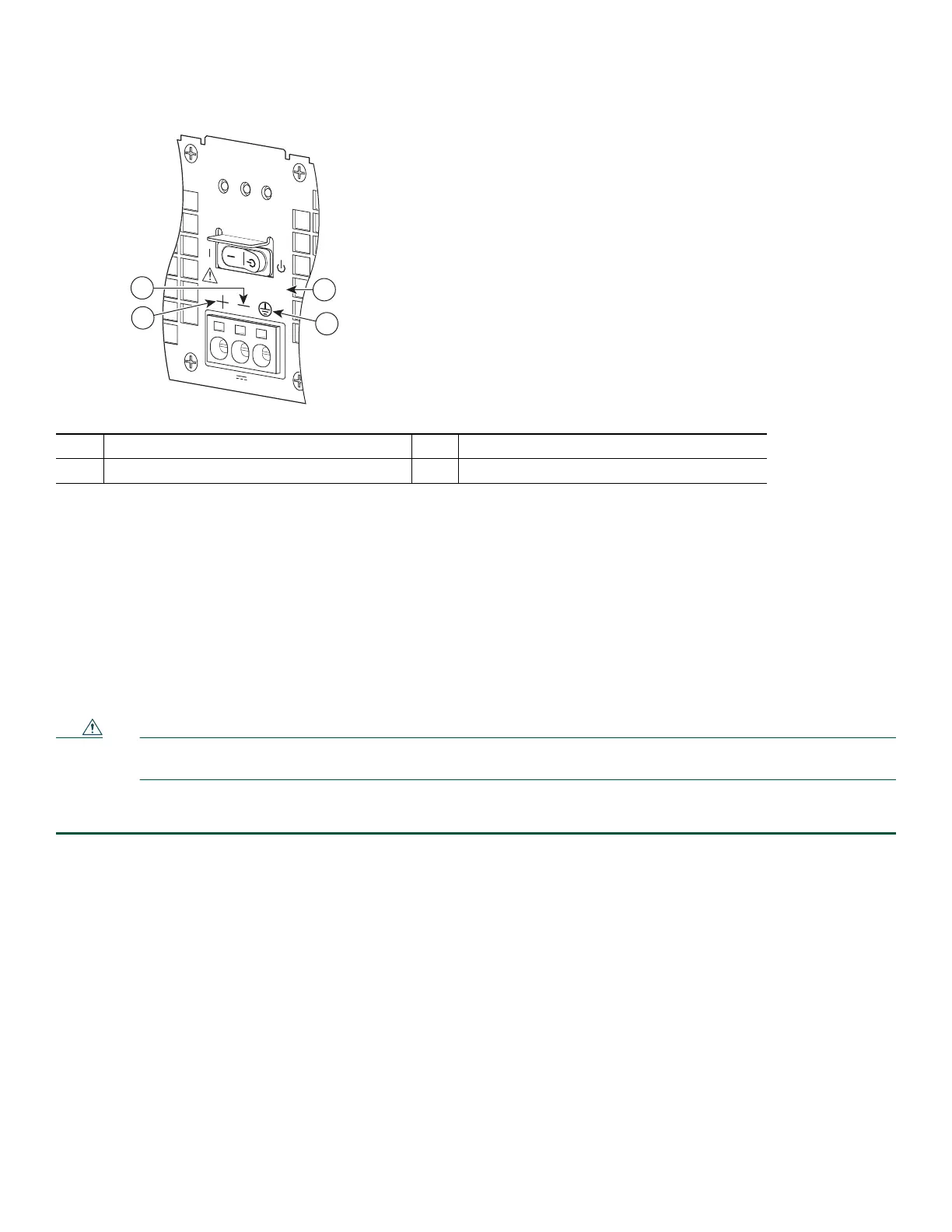
Figure 24 Cisco ASR 1002-X Router +24V DC Power Supply Terminal Block and Labels
• The ground (GND) lead is always installed first and removed last.
• The +24V DC power supply uses a spring loaded terminal block; therefore have the recommended screwdriver size
available.
• Review the diagrams to see how the wire is stripped and how the screwdriver is inserted at an angle into the terminal block.
• Have the following equipment available to install and remove the +24V DC power supply:
–
Phoenix Contact 3.5mm flat-blade screwdriver or equivalent
–
Wire-stripping tool for stripping 8-gauge wire
Before you can remove a +24V DC power supply from the Cisco ASR 1002-X Router, you must remove input power going to
the power supply.
Caution Make certain that the chassis ground lead wire is connected before you begin removing and installing the power
supply.
To remove the +24V DC power supply from the Cisco ASR 1002-X Router, follow these steps:
Step 1 Slip on the ESD-preventiveESD-preventive wrist strap that was included in the accessory kit.
Step 2 Place the power supply Standby switch in the Standby position.
Step 3 Using the recommended screwdriver, insert the screwdriver at an angle, pushing forward to release the internal spring
contact on the lead wire and then gently pull out the wire.
The screwdriver remains pushed into the spring release opening until the wire is completely removed.
1 Positive (+) lead 3 Ground (GND) lead
2 Negative (-) lead 4 +27V DC label
253165
OUTPUT INPUT
FAIL
OK OK
FAN
This unit might have more than
one power supply connection.
All connections must be removed
to de-energize the unit.
+27V DC INPUT
+27V 32A
1
2
4
3

 Loading...


