To comply with the intra-building lightning surge requirements of Telecordia GR-1089-CORE, Issue II,
Revision 01, February 1999, you must use a shielded cable when connecting the management LAN ports on
the RP card. The shielded cable is terminated by shielded connectors on both ends, with the cable shield
material tied to both connectors.
Note
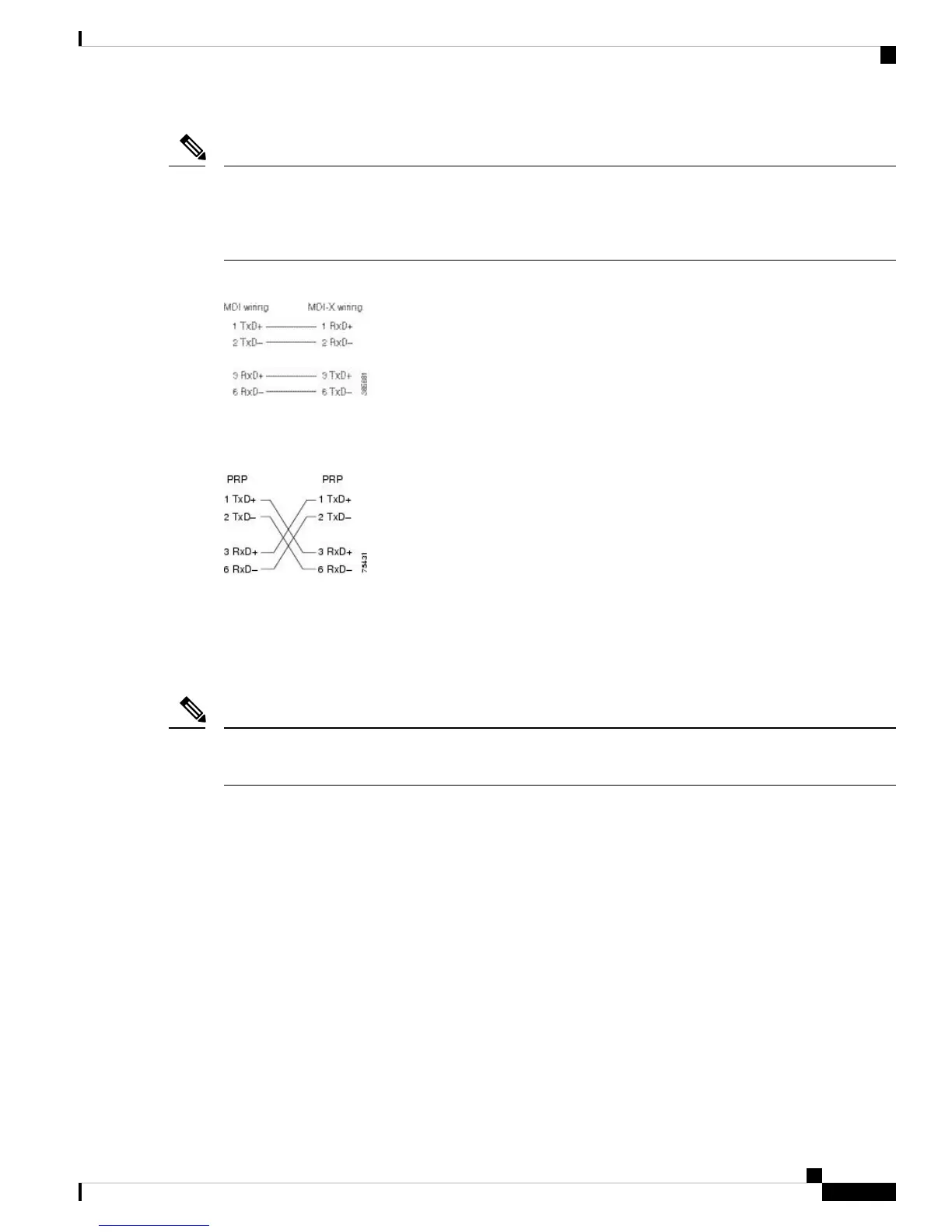
Figure 56: Straight-Through Cable Pinout to a Hub, Repeater or Switch
When connecting to a router, use the crossover cable pinout shown in the figure below.
Figure 57: Crossover Cable Pinout Between RP
Sync Ports Connection Guidelines
The SYNC 0 and SYNC 1 ports are timing synchronization ports. They can be configured as Building Integrated
Timing Supply (BITS) ports or J.211 ports.
Both ports must be configured to be in the same mode. It is not possible to use external BITS and J.211 sources
at the same time.
Note
When configured as BITS ports, they provide connections for an external synchronization source. Such
connections are for establishing precise frequency control at multiple network nodes, if required for your
application. The RP card contains a synchronous equipment timing source (SETS) that can receive a frequency
reference from an external BITS timing interface or from a clock signal recovered from any incoming Gigabit
Ethernet or 10-Gigabit Ethernet interface. The RP SETS circuit filters the received timing signal and uses it
to drive outgoing Ethernet interfaces.
The BITS input can be T1, E1 or 64K 4/. The BITS output can be T1, E1 or 6.312M 5/.
When configured as J.211 ports, they can be used as Universal Timing Interface (UTI) ports to synchronize
timing across multiple routers by connecting to an external timing source.
SYNC Port LED Indicators
The SYNC port connector has integral LED indicators (see the following figure). When lit, these LEDs
indicate:
Preparing for Installation
41
Preparing for Installation
Sync Ports Connection Guidelines

 Loading...


