1-28
Cisco ASR 9000 Series Aggregation Services Router Overview and Reference Guide
OL-17501-09
Chapter 1 Overview and Physical Description
Route Switch Processor and Route Processor Cards
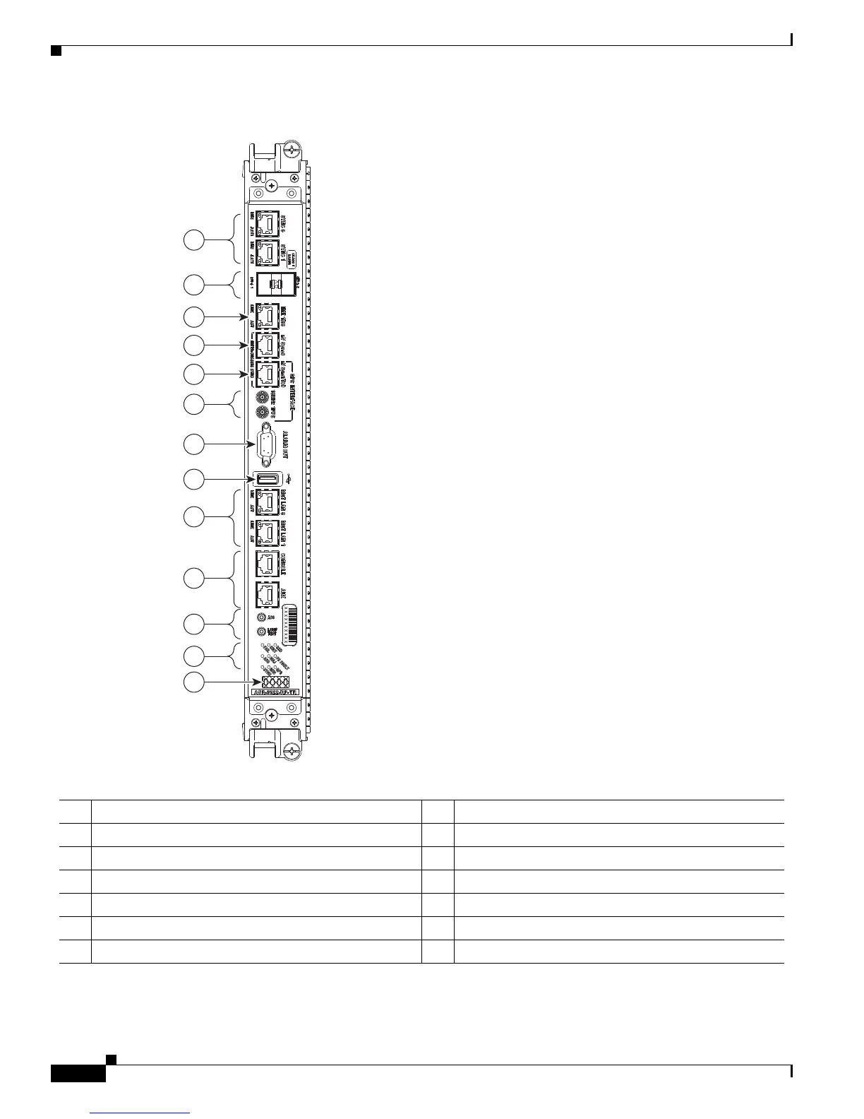
Figure 1-25 RP Card Front Panel
Figure 1-26 shows the RP card.
1 SYNC (BITS/J.211) ports 8 External USB port
2 SFP/SFP+ ports 9 Management LAN ports
3 IEEE 1588 port 10 CONSOLE and AUX ports
4 Inter-chassis nv Sync0 11 Alarm Cutoff (ACO) and Lamp Test push buttons
5 Inter-chassis nv Sync1 GPS ToD 12 Nine discrete LED indicators
6 10 MHz and 1 PPS indicators 13 LED matrix display
7 Alarm Out DB9 connector

 Loading...


