2-33
Cisco Integrated Services Router Hardware Installation Guide
Chapter 2 Installing the Router
Installing the Cisco 810 ISR
Configuring the Mount
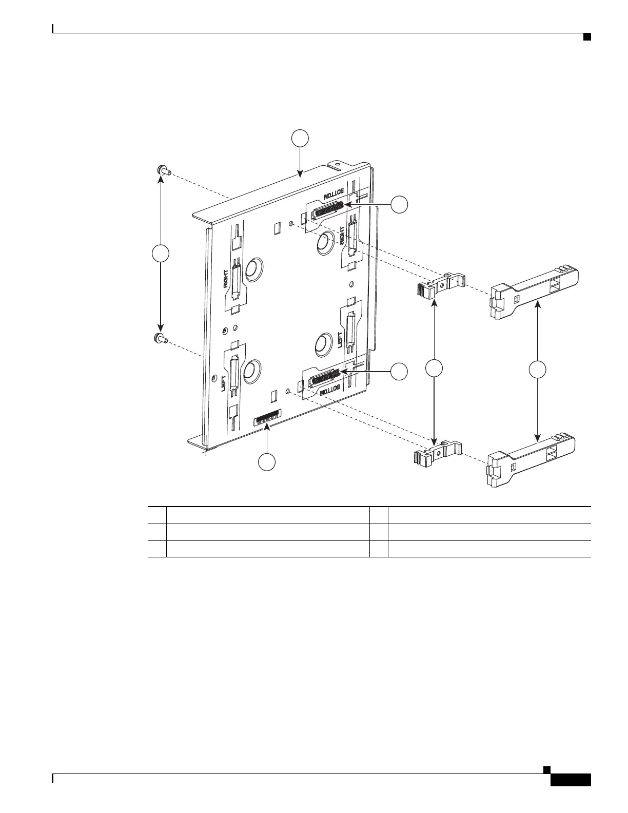
Figure 2-31 Low Profile DIN Mount Configuration
The mount comes configured in a bottom cable exit position, with the rail latches in the slots marked
Bottom. To reconfigure the mount:
1. Remove the two DIN Rail Latch Bracket Screws (Item 2).
2. Slide the DIN Rail Latch Brackets (Item 5) and DIN Rail Latch (Item 6) against the spring pressure,
towards the edge of the tray and remove the bracket and latch assembly. Be careful not to lose the
springs.
3. Remove the DIN Rail Latch Springs (Item 4)
4. Identify the desired mounting configuration and replace the latch assemblies in slots with the
matching labels, using the reverse order of steps 1 through 3.
1 Mount tray 4 DIN Rail Latch Springs
2 DIN Rail Latch Bracket Screws 5 DIN Rail Brackets
3 Mount Serial Number 6 DIN Rail Latch
 Loading...