Configure RP-TNC Antennas on
C9115AXE/C9120AXE/C9120AXP Access Points
Contents
Introduction
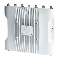
On the C9115AXE, C9120AXE and C9120AXP access points, the mapping of the radios' internal transceivers, to the
labeled Reverse Polarity Threaded Neill-Concelman (RP-TNC) ports on the AP ("A", "B", "C", "D"), is different for the
Slot 1 (dedicated 5 GHz) radio, than for the Slot 0 (XOR) radio. This article explains how the antenna mapping works,
and describes the options for configuring RP-TNC antennas with these AP models.
Mapping to RP-TNC Ports
On the C9115AXE, C9120AXE and C9120AXP access points, the mapping of the radios' transceivers to the
labeled RP-TNC ports on the AP ("A", "B", "C", "D") works like this:
For the Slot 0 radio (interface Dot11Radio0, the XOR radio), what the software calls "Antenna A"
maps to physical RP-TNC port "A", "Antenna B" maps to port "B", "Antenna C" to port "C", and
"Antenna D" maps to port "D"
•
However, for the Slot 1 radio (interface Dot11Radio1, the dedicated 5 GHz radio), what the software
calls "Antenna A" maps to physical RP-TNC port "D", "Antenna B" maps to port "C", "Antenna C"
to port "B", and "Antenna A" to port "D"
•
Configuration Restrictions