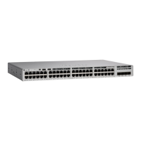
PoE and PoE+ Ports
The PoE and PoE+ ports provide the following functionality:
• PoE/PoE+ ports: Support for IEEE 802.3af-compliant powered devices (up to 15.4W PoE per port) and
support for IEEE 802.3at-compliant powered devices (up to 30W PoE+ per port).
• Support for pre-standard Cisco powered devices.
• Configurable support for Cisco intelligent power management, including enhanced power negotiation,
power reservation, and per-port power policing.
See the Power Supply Modules, on page 8 for the power supply matrix that defines the available PoE and
PoE+ power per port. The output of the PoE+ circuit has been evaluated as a Limited Power Source (LPS)
per IEC 60950-1.
Management Ports
The management ports connect the switch to a PC running Microsoft Windows or to a terminal server.
• Ethernet management port. See Ethernet Management Port, on page 10.
• RJ-45 console port (EIA/TIA-232). See RJ-45 Console Port, on page 10.
• USB mini-Type B console port (5-pin connector).
The 10/100/1000 Ethernet management port connection uses a standard RJ-45 crossover or straight-through
cable. The RJ-45 console port connection uses the supplied RJ-45-to-DB-9 female cable. The USB console
port connection uses a USB Type A to 5-pin mini-Type B cable. The USB console interface speeds are the
same as the RJ-45 console interface speeds.
If you use the USB mini-Type B console port, the Cisco Windows USB device driver must be installed on
any PC connected to the console port (for operation with Microsoft Windows). Mac OS X or Linux do not
require special drivers.
The 4-pin mini-Type B connector resembles the 5-pin mini-Type B connectors. They are not compatible. Use
only the 5-pin mini-Type B.
Figure 3: USB Mini-Type B Port
This illustration shows a 5-pin mini-Type B USB port.
With the Cisco Windows USB device driver, you can connect and disconnect the USB cable from the console
port without affecting Windows HyperTerminal operations.
The console output always goes to both the RJ-45 and the USB console connectors, but the console input is
active on only one of the console connectors at any one time. The USB console takes precedence over the
RJ-45 console. When a cable is connected into the USB console port, the RJ-45 console port becomes inactive.
Conversely, when the USB cable is disconnected from the USB console port, the RJ-45 port becomes active.
You can use the command-line interface (CLI) to configure an inactivity timeout which reactivates the RJ-45
console if the USB console has been activated and no input activity has occurred on the USB console for a
specified time.
Cisco Catalyst 9200 Series Switches Hardware Installation Guide
4
Product Overview
PoE and PoE+ Ports
 Loading...

