Console Port Mode 2 Signaling and Pinouts
This section provides the signaling and pinouts for the console port in mode 2 (port mode switch in the
"out" position). See Table I-4 for the pinouts. Mode 2 gives you the option of using a standard RJ-45
straight-through cable to connect a terminal.
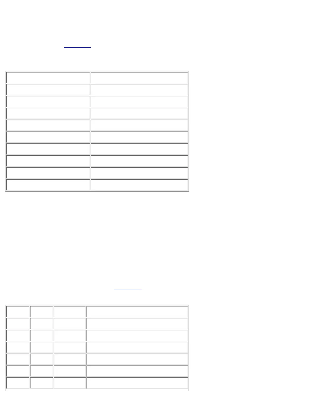
Table I-4: Console Port Pinouts (Port Mode Switch Out)
Console Port Console Device
Pin (signal) Input/Output
1 (RTS)¹ Output
2 (DTR) Output
3 (RxD) Input
4 (GND) GND
5 (GND) GND
6 (TxD) Output
7 (DSR) Input
8 (CTS)¹ Input
¹Pin 1 is connected internally to Pin 8.
Catalyst 8510CSR, and 8540CSR Switches Console
Port Pinouts
The console port on the route processor is an EIA/TIA-232, data communications equipment (DCE),
DB-25 receptacle. Both Data Set Ready (DSR) and Data Carrier Detect (DCD) are active when the
system is running. The Request To Send (RTS) signal tracks the state of the Clear To Send (CTS) input.
The console port does not support modem control or hardware flow control. The console port requires a
straight-through EIA/TIA-232 cable. Table J-1 lists the console port pinouts.
Table J-1: DB-25 Console Port Pinouts
Pin Signal Direction Description
1 GND Ground
2 TxD < Transmit Data
3 RxD > Receive Data
4 RTS > Ready To Send¹
5 CTS > Clear To Send¹
6 DSR > Data Set Ready (always on)²
 Loading...


