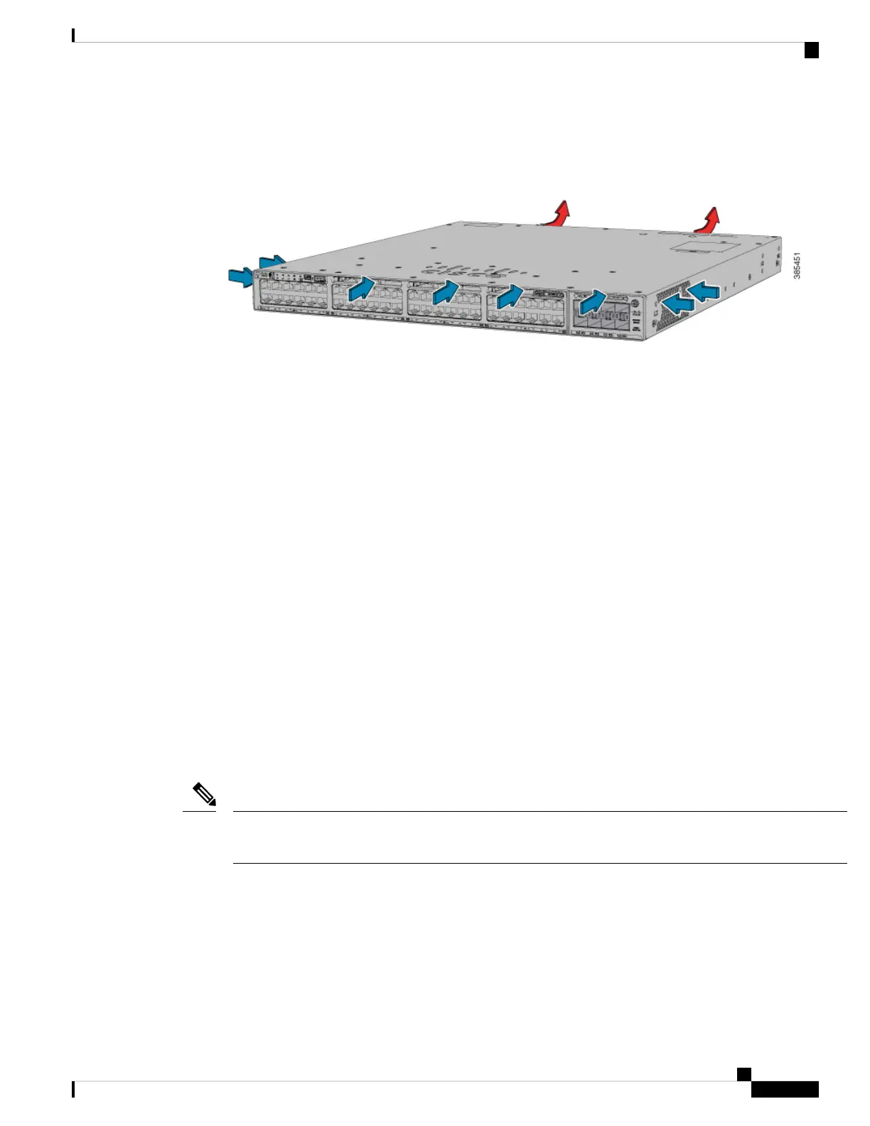
The airflow direction is from front-to-rear and side-to-rear. The following illustration shows the airflow pattern
for the switches. The blue arrow shows cool airflow, and the red arrow shows warm airflow.
Figure 15: Switch Airflow Pattern
For information about installing a fan module and fan specifications, see Installing a Fan Module, on page
98.
StackPower Connector
The C9300 switches have a StackPower connector for use with Cisco StackPower cables to configure a switch
power stack that includes up to four switches. A switch power stack can be configured in redundant or
power-sharing mode.
You can order these StackPower cables from your Cisco sales representative:
• CAB-SPWR-30CM (0.3-meter cable)
• CAB-SPWR-150CM (1.5-meter cable)
For details about connecting StackPower cables and StackPower guidelines, see Planning a StackPower Stack,
on page 51.
USB 3.0 SSD Port
To support the storage needs on the switch, the Cisco Catalyst 9300 Series Switches provide support for
pluggable 120 GB and 240 GB USB 3.0 Solid State Drive (SSD) modules. The USB 3.0 SSD module slot is
located at the rear panel of the switch. The storage drive can also be used to save packet captures and trace
logs generated by the operating system. The USB 3.0 SSD device is field replaceable.
C9300LM switches that have a mount kit to install SSD-240G on the USB Type A port on the front panel.
For more information, see Installing an SSD Module on C9300LM Switches.
Note
For information about installing a USB 3.0 SSD module, see Installing a USB 3.0 SSD, on page 101.
Ethernet Management Port
You can connect the switch to a host such as a Windows workstation or a terminal server through the
10/100/1000 Ethernet management port or one of the console ports. The 10/100/1000 Ethernet management
port is a VPN routing/forwarding (VRF) interface and uses a RJ-45 crossover or straight-through cable.
Cisco Catalyst 9300 Series Switches Hardware Installation Guide
29
Product Overview
StackPower Connector
 Loading...