Proper ESD protection is required whenever you handle Cisco equipment. Installation and maintenance
personnel should be properly grounded by using ground straps to eliminate the risk of ESD damage to the
switch.
Do not touch connectors or pins on component boards. Do not touch circuit components inside the switch.
When not in use, store the equipment in appropriate static-safe packaging.
Caution
• The switch meets the voltage dips and interruptions requirements of IEC 61850-3 only when powered
by a redundant power supply configuration.
• If you are responsible for the application of safety-related programmable electronic systems (PES), you
need to be aware of the safety requirements in the application of the system and be trained in using the
system.
• For better EMC performance, it is suggested to use S/UTP or SF/UTP cables for copper Ethernet ports.
Refer ISO/IEC11801 standard for details on S/UTP and SF/UTP.
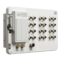
The device is designed to mount on a DIN rail that conforms to Standard EN60715.
Caution
In order to prevent excessive side to side movement of the unit it is advised to install DIN rail stop plates such
as mouser part numbers 653-PFP-M, 651-1201662 or 845-CA402. These end stops can be installed on one
or both sides or the unit to limit excessive side to side movement that typically occurs in high vibration
environments.
Note
When determining where to place the switch, observe these guidelines:
• Before installing the switch, first verify that the switch is operational by powering it on and observing
boot fast. Follow the procedures in the Verifying Switch Operation, on page 27.
• For 10/100/1000 ports, the cable length from a switch to an attached device cannot exceed 328 feet (100
meters).
• Clearance to front and rear panels meets these conditions:
• Front-panel LEDs can be easily read.
• Access to ports is sufficient for unrestricted cabling.
• Front-panel direct current (DC) power connectors and the alarm connector are within reach of the
connection to the DC power source.
• Airflow around the switch must be unrestricted. To prevent the switch from overheating, you must have
the following minimum clearances:
• Top and bottom: 2.0 in. (50.8 mm)
• Sides: 2.0 in. (50.8 mm)
• Front: 2.0 in. (50.8 mm)
Switch Installation
4
Switch Installation
General Guidelines
 Loading...