Lower horizontal cable
guide assembly
6Upper grille2
Lower bezel7Upper horizontal cable
guide
3
Middle horizontal cable
guide with strike tube
attached
4
Installing the Front (SFC) Side Cosmetic Components
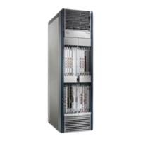
This section describes how to install the front (SFC) side exterior cosmetic covers on the FCC. Figure 1: FCC
Front (SFC) Side Exterior Cosmetic Components—Fixed Configuration Power Shown, on page 2 shows
the exterior cosmetics for the front (SFC) side of a chassis with fixed configuration power shelves installed.
The front view of an FCC with modular configuration power shelves installed is similar.
While it is possible to install the various front exterior components on the chassis in a different order, it
is easier to install them in the order outlined in this section.
Note
This section describes how to perform the following tasks:
Prerequisites
Before performing this task, you must first unpack and secure the chassis. See Cisco CRS Carrier Routing
System Fabric Card Chassis Unpacking, Moving, and Securing Guide .
Required Tools and Equipment
You need the following tools and part to perform this task:
• 8-in. long number 1 Phillips screwdriver—magnetic head preferable
•
10-mm hex key wrench
•
2-mm hex key wrench (for adjusting door set screws)
•
Torque wrench with 10-mm hex key and rated accuracy at 40 to 50 in-lb. (4.52 to 5.65 N-m)
•
Front cosmetic kit (Cisco product number: CRS-FCC-FRNT-CM=)
•
Front doors (Cisco product number: CRS-FCC-DRS-FR=)
Steps
To install the front (SFC) side exterior cosmetic components, perform the following steps:
Cisco CRS Carrier Routing System Fabric Card Chassis Installation Guide
4
Installing and Removing Exterior Cosmetic Components
Installing the Front (SFC) Side Cosmetic Components

 Loading...