The right unistrut (as you face the front [SFC] side of the chassis) has a cutaway in the rear to admit the chassis
ground cable; the left strut does not.
Note
Cisco recommends an install torque range for the unistrut bolts between 40 and 50 to in-lb. (between 4.52
N-m and 5.65 N-m).
Caution
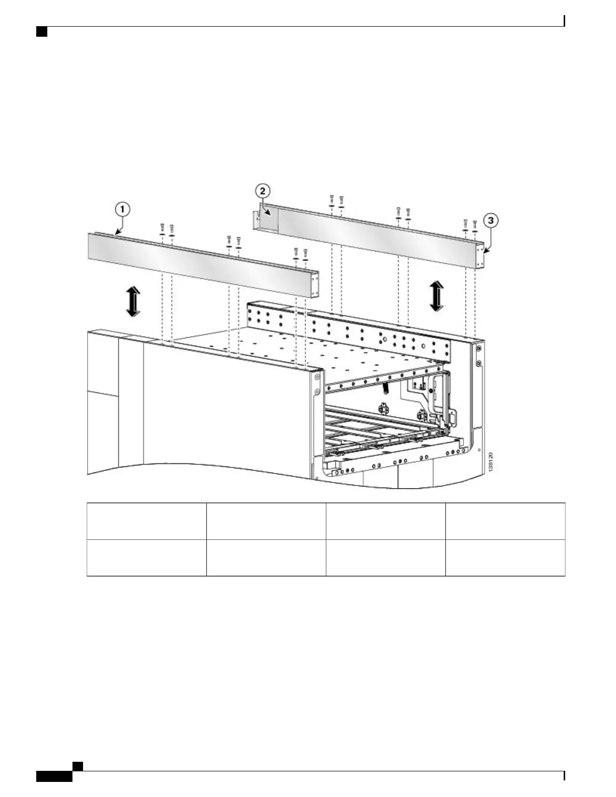
Figure 3: Attaching the Unistrut
Closed end at front of
unistrut
3Left unistrut1
Right strut with cutaway at
rear
2
Step 2
Attach the front upper grille support (number 1 in the figure below) to the unistruts by inserting four M4x14-mm flat
head screws, two for each unistrut, through the holes at the top of the front vertical cable troughs and tightening them
to the unistruts with the screwdriver.
Both fixed configuration power shelves must be installed in the chassis before installing the power shelf shutoff
extenders. See the chapter Installing and Removing Power Components for more information.
Note
Cisco CRS Carrier Routing System Fabric Card Chassis Installation Guide
6
Installing and Removing Exterior Cosmetic Components
Steps

 Loading...


