14 4028315 Rev A
Back Panel Description
Back Panel Description
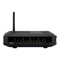
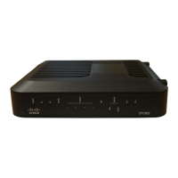
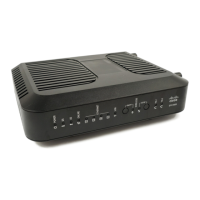
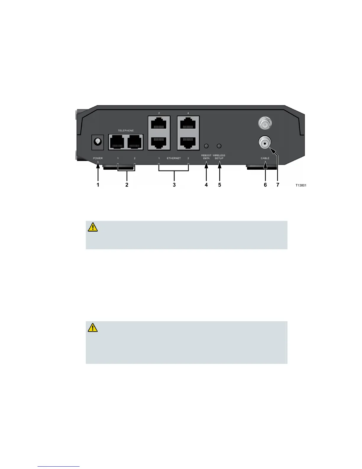
The following illustrations show the description and function of the back panel
components on the EPC2425.
External Power Supply Model
Model EPC2425 (with external power supply)
1 15VDC—Connects the residential gateway to the AC power adapter that
is provided with your residential gateway
CAUTION:
Avoid damage to your equipment. Only use the power supply
that is provided with your residential gateway.
2 TELEPHONE 1 and 2—RJ-11 telephone ports connect to home telephone
wiring to conventional telephones or fax machines
3 ETHERNET—Four RJ-45 Ethernet ports connect to the Ethernet port on
your PC or your home network
4 REBOOT EMTA—A momentary pressing (1-2 seconds) of this switch
reboots the EMTA. Pressing the switch for more than ten seconds first
causes a reset-to-factory-default of all settings and then reboots the
gateway
CAUTION:
The Reset button is for maintenance purposes only. Do not use
unless instructed to do so by your cable or telephone service
provider. Doing so may cause you to lose any cable modem
settings you have selected.
5 WIRELESS SETUP—Pressing this switch initiates wireless setup, this
feature allows the user to add new Wireless Protected Setup (WPS)
compliant wireless clients to the home network
6 CABLE—F-connector connects to an active cable signal from your service
provider
7 ANTENNA—Connection for external 802.11 antenna
 Loading...