c) Slide the release clip toward the rear on both inner rails, and then continue pushing the chassis into the rack until the
mounting brackets meet the front of the slide rail.
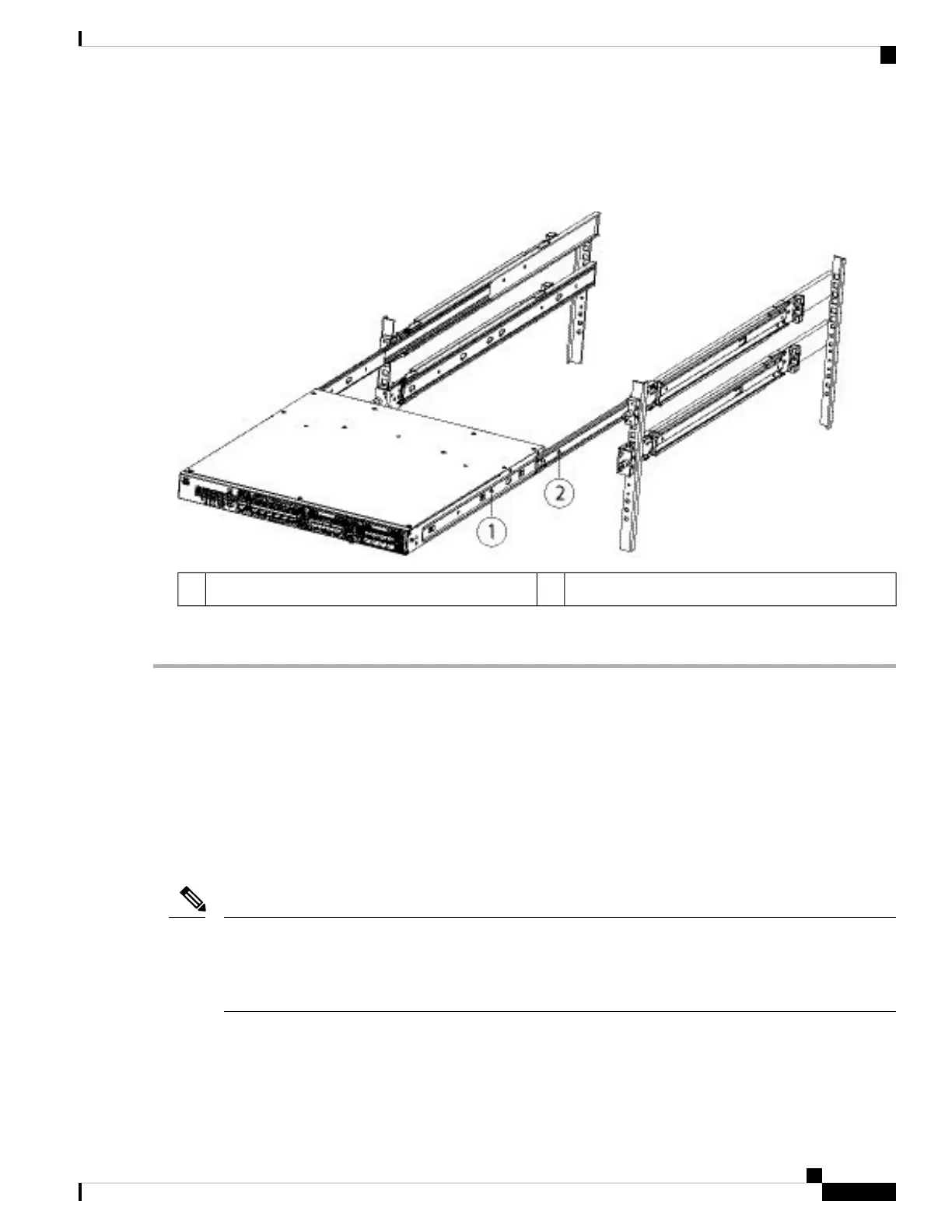
Figure 8: Inner Rail Release Clip
Inner rail attached to chassis2Inner rail release clip1
Step 7 Use the captive screws on the front of the mounting brackets to fully secure the chassis to the rack.
What to do next
• See Ground the Chassis, on page 9 for the procedure to ground the Firepower 2100.
• Install the cables according to your software configuration as described in the Cisco Firepower 2100
Getting Started Guide.
Ground the Chassis
Grounding the chassis is required, even if the rack is already grounded. A grounding pad with two threaded
M4 holes is provided on the chassis for attaching a grounding lug. The grounding lug must be Nationally
Recognized Testing Laboratory (NRTL)-listed. In addition, a copper conductor (wires) must be used and the
copper conductor must comply with National Electrical Code (NEC) code for ampacity.
Note
You need the following items that you provide:
• Wire-striping tool
• Crimping tool
Rack-Mount and Ground the Chassis
9
Rack-Mount and Ground the Chassis
Ground the Chassis
 Loading...


