◦
Balances the two line losses by changing the VOA attenuation value at the same time of the switch
change of state.
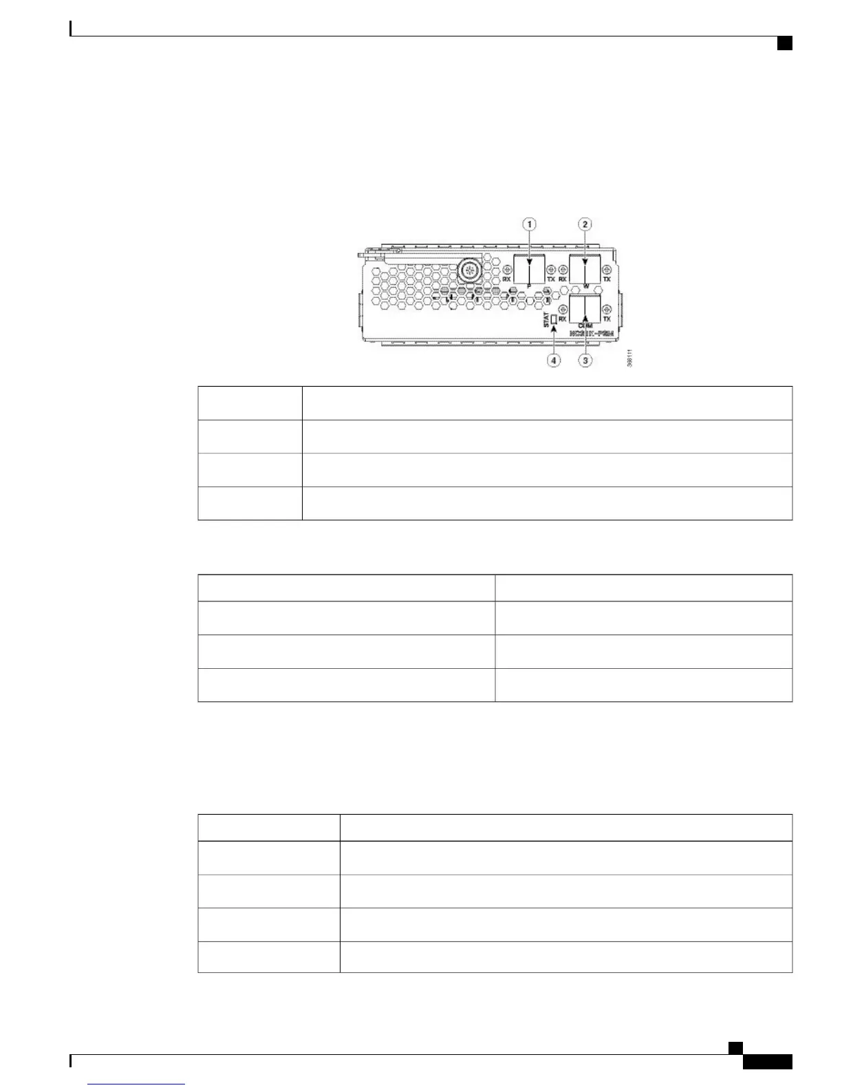
Figure 6: PSM Front View
Protected path input and output port [P - RX, TX]1
Working path input and output port [W - RX, TX]2
COM input and output port [COM - RX, TX]3
Status LED4
The following table describes the mapping of controllers and optical ports for the protection switching module.
Optical PortsController
COM-TXOts 0/slot/0/0
Working path input and output port [W - RX, TX]Ots 0/slot/0/1
Protected path input and output port [P - RX, TX]Ots 0/slot/0/2
Product IDs
The following table describes the product IDs of the components.
DescriptionProduct ID
Network Convergence System 1001 line system 3 slotsNCS1001-K9=
Network Convergence System 1001 Control cardNCS1K-CNTLR2=
Network Convergence System 1001 amplifier moduleNCS1K-EDFA=
Network Convergence System 1001 protection moduleNCS1K-PSM=
Hardware Installation Guide for Cisco NCS 1001
7
Cisco NCS 1001 Overview
Product IDs
 Loading...