1
Unpack the foot module (stand-alone, wall mounting or wheelbase)
Lift out to open
the snap lockers
2
Remove the outer cover and locate the boxes for the monitor, column, camera, touch screen and accessories
C Wheelbase foot module
3
C: Mounting the wheelbase foot module
The accessories box contains:
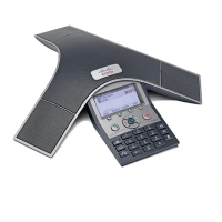
• Microphones, 2 or 3 pcs.
• Remote control and 4 AAA
batteries
• Cleaning cloth
• Power cables
• Two M8 ×60 screws
PRECAUTIONS
Please follow the steps in this installation guide when unpacking
and assembling Profile 42”/52”. A minimum of two (2) persons are
required when installing Profile 42”/52”.
UNPACKING THE SYSTEM AT THE DESTINATION
It is highly recommended to start the unpacking and assembling of
Profile 42”/52” at the place where the system is to be used.
NOTE: If it is not possible to bring the complete delivery to the room
where Profile 42”/52” is to be used, then unpack (step 1–2) and
bring the smaller units to the destination.
• The monitor box requires two (2) persons to lift
(42” 110 lb / 50 kg, 52” 132 lb / 60 kg)
• The column requires two (2) persons to lift (55 lb / 25 kg)
• The stand-alone foot module requires two (2) persons to lift (55 lb /
25 kg)
INSTALLATION NEAR A SOCKET-OUTLET
The equipment must be installed near a socket-outlet. The socket-
outlet shall be easily accessible after installation.
ROOM GUIDELINES
NOTE: The floor must be in level.
The recommended distance between the Profile 42”/52” and
the meeting room table should be minimum 59 in. / 150 cm.
Read more about room guidelines in the Video conferencing room
primer.
USER DOCUMENTATION
The user documentation for this product, including compliance and
safety information, is available on the Cisco web site.
Go to: http://www.cisco.com/go/telepresence/docs.
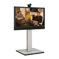
DIMENSIONS OF PROFILE 42”
The assembled unit has the following dimensions:
• Height: 59.9 in. / 152 cm
• Width: 38.6 in. / 98 cm
• Depth: Stand-alone: 26.8 in. / 68 cm
Wall mounting: 8.9 in. / 23 cm (brackets included)
Wheelbase: 31.8 in. / 81 cm
• Weight: 231.5 lb / 105 kg
DIMENSIONS OF PROFILE 52”
The assembled unit has the following dimensions:
• Height: 63.6 in. / 162 cm
• Width: 47.4 in. / 121 cm
• Depth: Same as for Profile 42”
• Weight: 253.5 lb / 115 kg
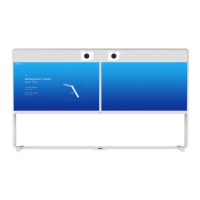
Profile 42”/52” contains:
Monitor
Bottom module:
• Column
• Foot module (stand-alone, wheelbase
or wall mounting)
Front grille (inside foot module box)
Speaker grille (inside monitor box)
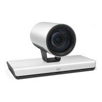
Camera
Microphones, 2 or 3 pcs.
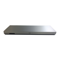
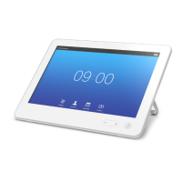
Touch Screen CS
Remote control
Cables, screws and tools
Cleaning cloth
1. Open the snap lockers.
2. Lift out the foot module box.
3. Open the box and unpack the
foot module.
A Stand-alone foot module (55 lb /25 kg)
CAUTION: You need two persons to mount the column
to the foot module. Take care to hold the modules firmly
during installation.
1. Unpack the column. Hold it firmly while moving the foot
module towards the bottom of the column, aligning the
holes for the screws.
2. Fasten the four M8×50 screws with the
Allen key.
3. Raise the bottom module.
CAUTION: You need two persons to mount the
column to the wheelbase. Take care to hold the
modules firmly during installation.
1. Unpack the column. Hold it firmly while moving
the wheelbase towards the bottom of the
column, aligning the holes for the screws.
2. Use the Allen key, which is
found in the foot module
box, to fasten the four
M8×30 screws.
3. Raise the complete
bottom module.
B Wall mounting foot module
Fastening the front grille
The front grille is attached using one M6×16 screw (upper
screw) and one M6×10 screw (lower screw) on each side, as
illustrated to the right. Use the Torx key.
The grille and Torx key are found in the foot module box. The
screws are premounted in the grille and bottom module.
Follow these steps to fasten the grille:
4. Remove the two upper screws from the grille.
5. Loosen the two lower screws in the bottom module
without removing them.
6. Place the front grille below the front door, as illustrated
to the right. Tilt the front grille to get the brackets behind
the front door and slide the grille on to the lower screws.
7. Open the front door to gain access to the screws.
a) Insert the upper screws without tightening them.
b) Close the front door to align the grille.
c) Open the front door again, and tighten the lower
screws through the hole.
d) Tighten the upper screws.
Hole to access
the lower screw
Front door
Front grille
Upper screw
(M6×16)
CAUTION
HEAVY
Camera
Accessories box
Touch screen
Monitor
(42” 110 lb / 50 kg,
52” 132 lb / 60 kg)