Cisco Unmanaged Rackmount Switches 4
STEP 3 Insert a screw into each hole, leaving a gap between the surface
and the base of the screw head of at least 0.1 inches (3 mm).
STEP 4 Place the unmanaged rackmount switch wall-mount slots over the
screws and slide the unmanaged rackmount switch down until the
screws fit snugly into the wall-mount slots.
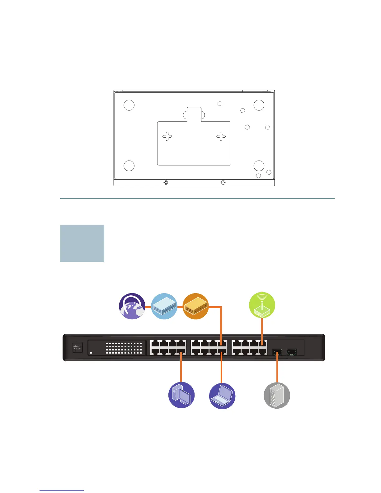
Connecting Network Devices
The application diagram is an example of a typical network configuration.
276583
123 4 5678 9101112
13 14 15 16 17 18 19 20 21 22 23 24
miniGBIC1
(Shared with 12) (Shared with 24)
miniGBIC2
Cisco Small Busine ss
SR2024
24-Por t
10/100/ 1000 Swit ch
1 2 3 4 5 6 7 8 9 1 0 11 12 /
miniGBIC1
Link/Act
Gigabit
Link/Act
Gigabit
SYSTEM
13 14 15 16 17 18 19 20 21 22 23 24 /
miniGBIC2
193803
 Loading...