18
IX5000 Field-Replaceable Units and Country- and Region-Specific Power Connectors
Replacing a Display—Part Number CTS-5K-70-G1=
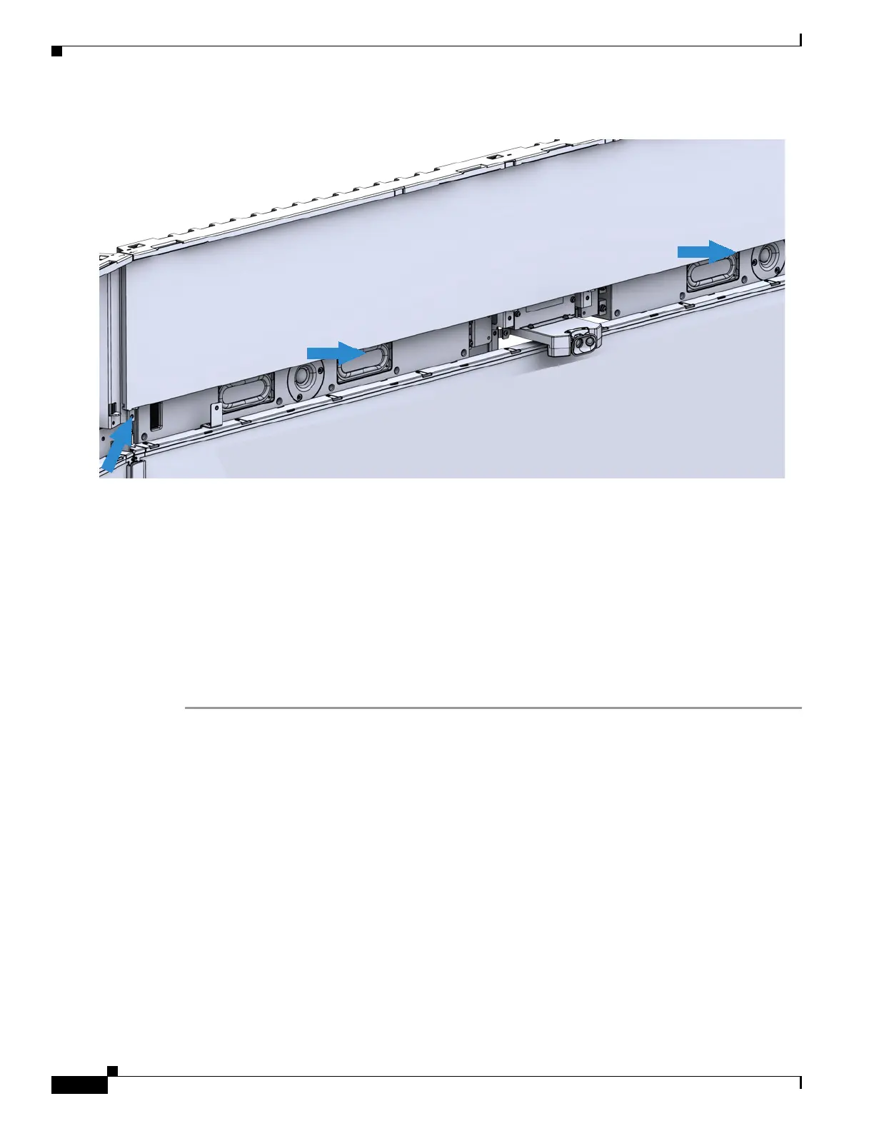
Step 7 Remove the camera by unscrewing the four captive screws that connect it to the endpoint structure.
Step 8 Install the new camera.
Step 9 Replace the center light panel and center speaker cover.
Step 10 Replace the upper facade and lens hood cover (camera cover).
Step 11 Power on the PDUs on the lower part of the endpoint structure.
Step 12 Log into the Cisco TelePresence Administrative UI and perform the camera alignment procedure.
Step 13 Replace the lower facade.
For detailed steps and additional illustrations, refer to the IX5000 installation guide and the first-time
setup chapter.
Replacing a Display—Part Number CTS-5K-70-G1=
Required Tools
#2 and #3 Phillips drivers.
 Loading...