[SMB-20E]
― 10 ―
ADEQUATE
OPERATION
4
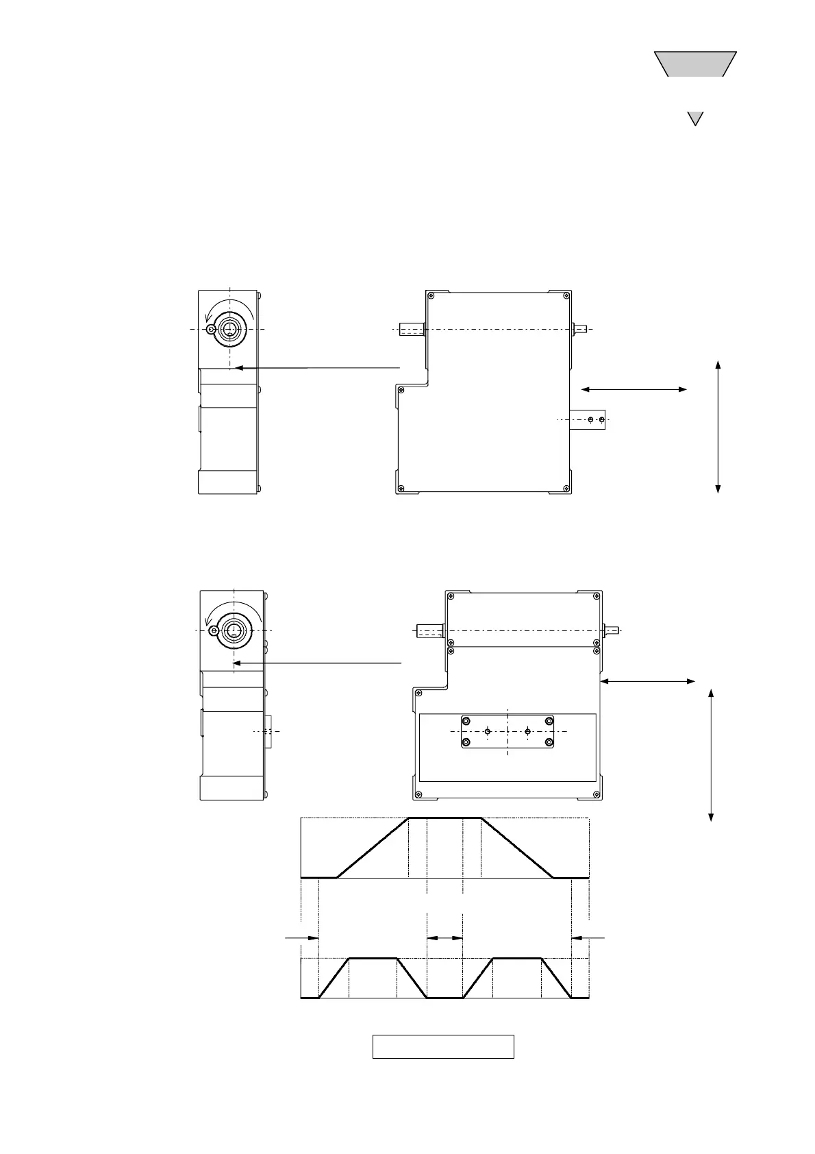
(3) Positional relationship between the timing chart and the key groove in the
input shaft
Start and stop the input shaft in the horizontal-direction and vertical-direction
retention zones (a, b) according to the positional relationship between the
timing chart determined and the input shaft.
Input shaft
direction
Position where cam
index angle is 0 degrees
Timing Chart (Example)
Stroke La
Position where cam
index angle is 0 degrees
Stroke La
Input shaft rotation angle(deg)
150゜
0゜
θa
50mm
0
360
θa
360
θb
Stroke La Stroke Lb
Input shaft rotation angle(deg)
Input shaft
direction
 Loading...