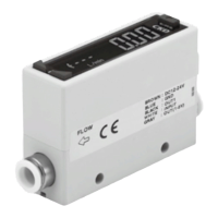
[2] Installation
■Arrange piping so that the flow
direction agrees with the direction
of the arrow indicated on the
sensor body.
■Flash the pipe to remove foreign substances and swarf, etc., in inside of
pipe before piping.
■When piping a sensor, do not apply excessive screw-in and load torques to the
port.
When piping, apply a spanner on the metal section not to apply forces
onto the resin section.
■When piping, care must be taken that sealing tape and adhesive must
not enter into the inside.
■If a push-in joint is used, the tube must be inserted certainly. Pulls the
tube to check that the tube not be come out.
■This product can be installed with any attitude; vertical, horizontal, right
or left.
The tightening torque for screws should be 0.5N・m.
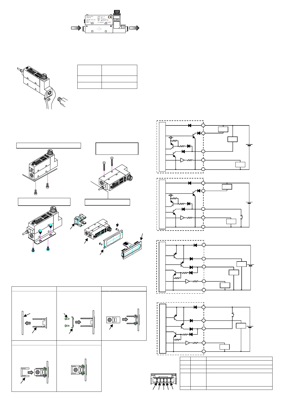
<How to panel mount>
[3] Piping
■Power supply voltage and outputs must be used with the specified
voltage. Applying the voltage more than specified voltage may cause
malfunction, damage of sensor, electric shock or fire.
Do not apply load more than the rated output. Damage or fire of the
output may be caused.
■For wiring, stop control unit/machinery and equipment, and turn off the
power supply.
■This product and wiring must be installed as far away as possible from noise
source such as strong electric line, etc. Take other countermeasures for a
surge on the power supply line.
■Do not short-circuit a load, or causing damage or burn.
■Line color must be checked when wiring. Check the wiring color with handling
precaution, since improper wire connection may result in damage, failure or
malfunction of the sensor.
■Use DC safety power supply thoroughly insulated from the AC primary side for
a power supply for the metal body (stainless steel and aluminum bodies) type,
while connecting either + or - side on the power supply to F.G.
■After the connectors are inserted, lay the connector covers over the
connectors. Make sure that stress by forcible bend of pulling is not applies
directly to the sensor cable joint.
●
Example of internal circuit and load connection
NPN output
Model no.: FSM2 -N[ ]-[ ]
<CH2 function selected switch output>
<CH2 function selected external input>
PNP output Model no.: FSM2 -P[ ]-[ ]
<CH2 function selected switch output>
<CH2 function selected external input>
[1] [2] [3]
The panel bessel is inserted
from the front side of the
panel.
The panel Bessel is inserted
from the back side of the
panel, and holding with the
screw.
The separation indicator is
inserted from the back side of
the panel.
[4] [5]
The panel holder is inserted
from the back side of the
panel.
The panel holder is
pushed until the sensor is
firmly fixed, and connector is
connected.
Note:
・Please do the piping work
before it works of the panel
mount, and please do not add
the stress to parts of the
panel mount.
・ Please fix by the tightening
torque of 0.06N・m when
you fix the panel bessel
suppression.
Set screw
Tightening torque
N・m
Rc1/8
3~5
Rc1/4
6~8
Bracket (separate sales)
Model no. : FSM2-LB1
Port size: Push-in joint φ4、6、8、10
Rc1/8、Rc1/4
Main circuit
Load
Load
Load
Brown (Power supply +)
Gra
Analo
out
ut
Black (CH1)
Switch out
ut 1
White (CH2)
Switch out
ut 2
Blue
Power su
l
-
+
2
3
4
5
1
Main circuit
Load
Load
White (CH2)
External in
u
+
2
3
4
5
1
Brown (Power supply +)
Black (CH1)
Switch out
ut 1
Gray (Analog output)
Pin No. Line color Content
[1] Brown Power supply (DC 12 to 24V, DC 24V)
[2] Black CH1(Switch output 1: max50mA)
[3] White
CH2(Switch output 2: max50mA or External input)
[4] Gray
Analog voltage output : DC 1 to 5V
Connected load impedance 50kΩ and over)
Analog current output : DC 4 to 20mA
Connected load impedance 300Ω or less)
[5] Blue 0V (GND)
※Analog output voltage output type R:about1kΩ
Current output type R:about100Ω
[1]
2
[3] [4] [5]
(FSM2 side)
Vertical mount(with bottom thread)
Horizontal mount
(with through hole)
Bracket mount (with bracket)
Main circuit
Load
Load
Load
Brown (Power supply +)
Gray (Analog output)
+
Black (CH1)
Switch out
ut 1
White (CH2)
Switch output 2
2
3
4
5
1
Blue (Power supply -)
Panel mount
Panel mount kit Model no.
:FSM2-KHS-N
Panel bessel suppression
Screw
Panel
Panel bessel
Sensor
Panel holder
Main circuit
Load
Load
Brown (Power supply +)
Gray (Analog output)
+
Black (CH1)
Switch out
ut 1
White (CH2)
External input
2
3
4
5
1
Blue (Power supply -)
Panel bessel
Panel bessel suppression
Scre
Panel holder
Sensor
-2-
R※
R※
R※
Blue
Power su
l
-
R※
 Loading...