3 4 5
CV
KH
YC
7
YF
1
MV
MP
FCA
SB1 SB2
KRX
6 2 X
PCB
R1 R2
FCM
KH
LPE N
Q1
1 3
2 4
21 11
1222
TV
M M
6 1
L
A1
A2
A2
A1
230V-50Hz
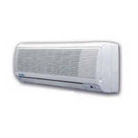
Unit for system with 4 pipes, with
two valves, or with 2 pipes, with or
without valve and electric heater,
with DRA control panel.
Jednostka dla systemu 2-rurowe-
go, z zaworem lub bez, z panelem
sterowania DRA.
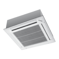
Unit for system with 2 pipes, with
or without valve, with DRA control
panel.
2.7 Instalacja elektryczna
Przed rozpoczęciem jakichkolwiek prac związanych z instalacją elektryczną
klimakonwektora, odłącz urządzenie od źródła zasilania, przełączając
główny wyłącznik. Zawsze pamiętaj o podłączeniu przewodu uziemiającego.
Uziemienie jest wymagane prawnie.
Do tego celu instalator powinien wykorzystać odpowiedni zacisk ozna-
czony międzynarodowym symbolem określającym miejsce podłączenia
uziemienia.
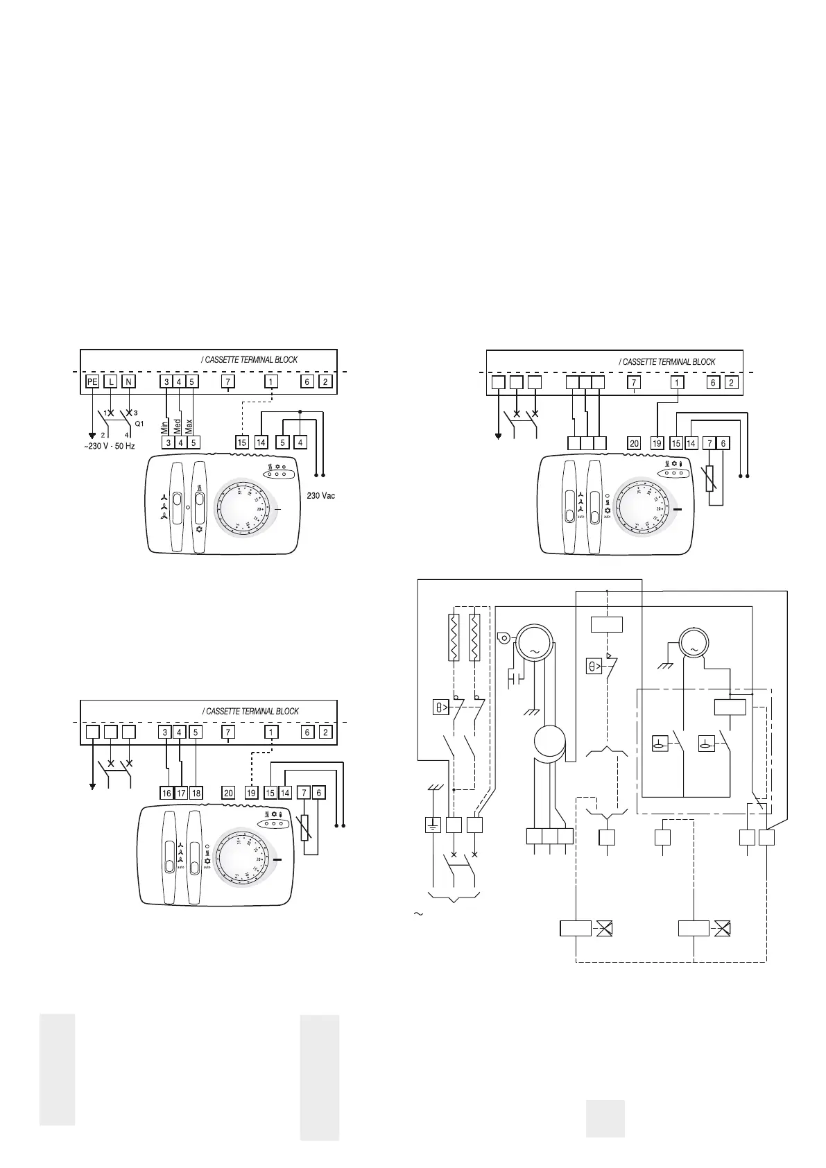
JEDNOSTKA DLA SYSTEMU 2 I 4 RUROWEGO: MODELE 42÷54
Schemat elektryczny: warianty konstrukcyjne mogą wymagać modyfi-
kacji, zawsze korzystaj ze schematu dołączonego do urządzenia.
2.7 Electrical connections
Before performing any work on the electrical part of the unit, turn off the
main switch. Always remember to connect the earth wire.
Earth connection is obligatory by law.
The installer must provide for it via the terminal marked with the interna-
tional earth symbol.
UNIT FOR 2 AND 4 PIPES SYSTEM: MO DELS 42÷54
Main layout: the variants made in the constructions can involve modifi -
cations. Always refer to the layout supplied with the product.
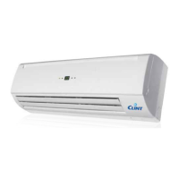
Jednostka dla systemu 2-rurowe-
go, z zaworem lub bez, z panelem
sterowania DRM.
Unit for system with 2 pipes, with
or without valve, with DRM con -
trol panel.
Jednostka dla systemu 4-rurowego
z dwoma zaworami lub dla systemu
2-rurowego, z zaworem lub bez,
grzałką elektryczną i panelem ste-
rowania DRA.
min
med
max
Minimalna prędkość
/
minimum speed
Średnia prędkość
/
medium speed
Maksymalna prędkość
/
maximum speed
CV Skraplacz / Condenser
FCA Zabezpieczenie automatyczne / Automatic protection
FCM Zabezpieczenie ręczne / Manual protection
KH Przekaźniki alarmowe / Alarm relais
L Faza / Phase
MP
Silnik pompki skroplin /
Drain pump motor
MV Silnik wentylatora / Fan motor
N Zero / Neutral
PCB Płytka elektroniczna / Electronic board
PE Uziemienie / Ground
Q1 Zabezpieczenie / Protection
R1/R2 Grzałka elektryczna / Electric heater
SB1/SB2 Czujnik poziomu wody / Water level sensor
SM Czujnik min. temperatury wody / Sensor min. water temp.
TV Autotransformator / Autotransformer
X Listwa zaciskowa / Power terminal block
YC Zawór 3-drogowy (4R) / 3-way valve (4 T)
YF Zawór 3-drogowy / 3-way valve
LISTWA ZACISKOWA KASETY
LISTWA ZACISKOWA KASETY
LISTWA ZACISKOWA KASETY
PE L N 3 4 5
16 17 18
N L
230 Vac
SM
~230 V - 50 Hz
Min
Med
Max
1
3
2 4
Q1
PE L N
N L
230 Vac
~230 V - 50 Hz
Min
Med
Max
1
3
2 4
Q1
SM
 Loading...