Prima di effettuare qualsiasi operazione sulla parte elettrica dell’unità
togliere l’alimentazione spegnendo l’interruttore generale. Ricordarsi
sempre di collegare il filo di terra.
Il collegamento a terra é obbligatorio per legge.
L’installatore deve provvedere alla sua realizzazione utilizzando l’appo-
sito morsetto contrassegnato dall’indicazione internazionale di messa
a terra.
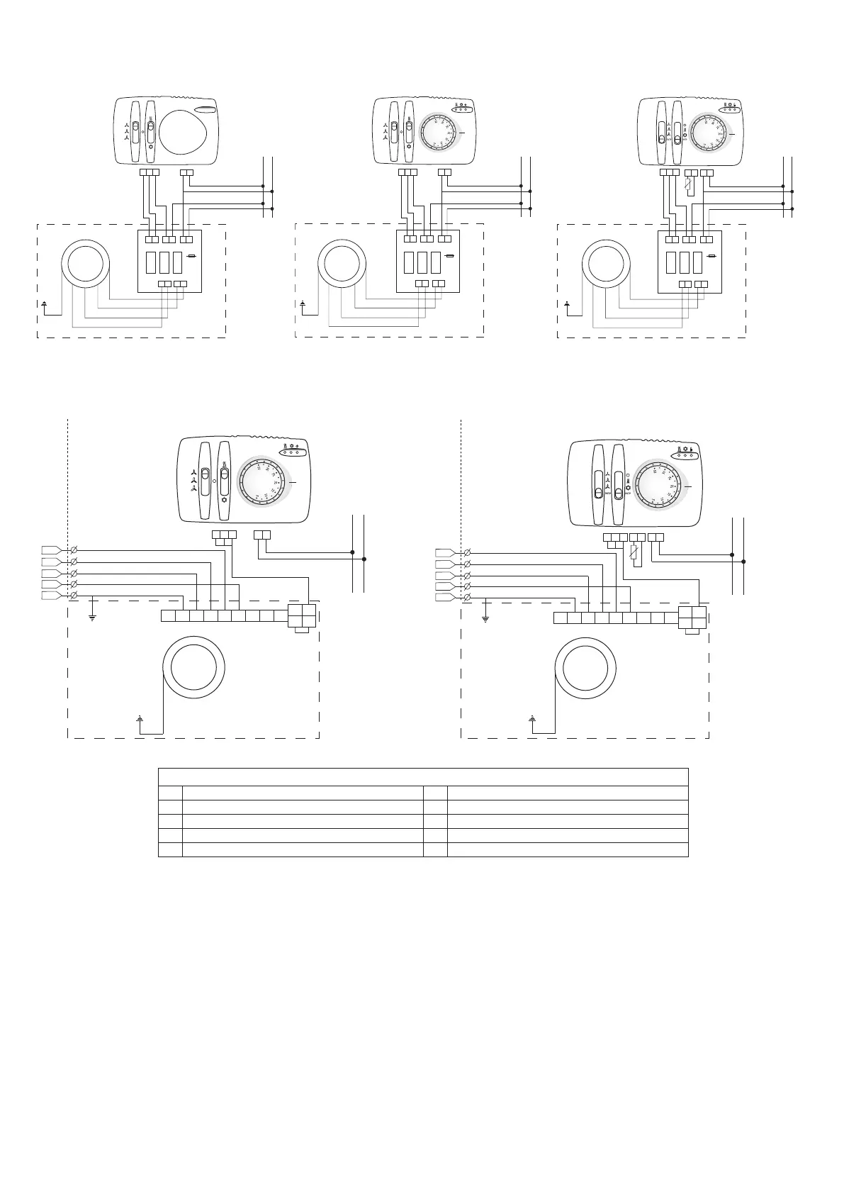
I collegamenti elettrici devono essere effettuati come da Fig. A per i
modelli dal 63 al 274 con pannelli di controllo VR oppure DRM oppure
DRA. I collegamenti elettrici devono essere effettuati come da Fig. B per
i modelli dal 333 al 544 con pannelli di controllo DRM oppure DRA.
2.3 Avviamento
Sfiatare l’impianto dopo averlo riempito.
Inoltre sfiatare l’unità per mezzo delle apposite valvoline e controllare il
buon funzionamento dell’unità.
Attenzione!
Il primo avviamento dell’unità deve essere effettuato alla massima
velocità, lasciando girare il ventilatore per circa 4/5 ore. Ripetere
l’operazione dopo una lunga inattività.
Before carrying out any operations on the electrical part of the units,
disconnect the electrical mains power supply by turning off the main
switch. Always remember to connect the earth wire.
The earth connection is required by law.
The installer must provide for its realization by using the appropriate
terminal which is marked with the international symbol for earth con-
nections.
The electrical connections must be made as shown in the picture A
for models 63÷274 with control panels VR or DRM or DRA. Electrical
connections must be as shown in picture B for models 333÷544 with
control panels DRM or DRA.
2.3 Start-up
Bleed the system after having filled it.
Also bleed the unit by means of the appropriate valves and check unit
for proper operation.
Attention!
The first start-up of the unit must be made at maximum speed,
letting the fan run for 4-5 hours. Repeat this operation after a long
shutdown period.
Schema elettrico DRM e DRA (solo mod 333÷544)
Schema elettrico VR, DRM e DRA (solo mod 63÷274)
2.2 Collegamenti elettrici
230 V - 50 Hz
L N
3~
M
4
5
1
2
3
F1 PE L1 L2 L3 N U V W
F 6
N N
1
N
PE
PE
400V / 3+N+PE
LINEA DI ALIMENTAZIONE PROTETTA DALL'INSTALLATORE
POWER LINE PREVIOUSLY PROTECTED BY
THE INSTALLER
L3
L2
L1
LIMITE FORNITURA / SUPPLY LIMIT
Motore / Motor
Giallo/Verde/Terra
Yellow/Green/Earthing
DRM
Unità trattamento aria
Air handling unit
230 V - 50 Hz
L N
3
~
M
16 17 18 15 14
F1 PE L1 L2 L3 N U V W
F 6
N N1
N
PE
PE
400V / 3+N+PE
LINEA DI ALIMENTAZIONE PROTETTA DALL'INSTALLATORE
POWER LINE PREVIOUSLY PROTECTED BY
THE INSTALLER
L3
L2
L1
LIMITE FORNITURA / SUPPLY LIMIT
Motore / Motor
DRA
Giallo/Verde/Terra
Yellow/Green/Earthing
6
7
SM
Fig. A
Fig. B
Legenda / Legend
N
Neutro / Neutral
N/N
Neutro / Neutral
V3
Uscita velocità max / Outlet max speed
L
Fase / Phase
V2
Uscita velocità med / Outlet min speed
3
Entrata velocità max / Inlet max speed
V1
Uscita velocità min / Outlet med speed
2
Entrata velocità med / Inlet min speed
SM
Sonda di minima / Minimun sensor
1
Entrata velocità min / Inlet med speed
230 V - 50 Hz
L N
~
M
6
7
8
9
10
1 2 3 L N N
N
RELÈ
RELÈ
RELÈ
V1 V2 V3
VR
Bianco comune/White Common
Motore 3 velocità
3 speed motor
Nero max / Black max.
Blu med / Blue med.
Rosso min / Red min.
Giallo/Verde/Terra
Yellow/Green/Earthing
230 V - 50 Hz
L N
~
M
1
2
3
4
5
1 2 3 L N N
N
RELÈ
RELÈ
RELÈ
V1 V2 V3
Bianco comune/White Common
Motore 3 velocità
3 speed motor
Nero
max / Black max.
Blu med / Blue med.
Rosso min / Red min.
Giallo/Verde/Terra
Yellow/Green/Earthing
DRM
230 V - 50 Hz
L N
~
M
18
17
16
15
14
1 2 3 L N N
N
RELÈ
RELÈ
RELÈ
V1 V2 V3
Bianco comune/White Common
Motore 3 velocità
3 speed motor
Nero max / Black max.
Blu med / Blue med.
Rosso min / Red min.
Giallo/Verde/Terra
Yellow/Green/Earthing
DRA
6
7
SM
Unità trattamento aria
Air handling unit
Unità trattamento aria
Air handling unit
Unità trattamento aria
Air handling unit
Unità trattamento aria
Air handling unit
2.2 Electrical connections
VR, DRM and DRA electric diagram (only models 63÷274)
DRM and DRA electric diagram (only models 333÷544)
 Loading...