M23740N6-03 01/10/07 page 11
WATER HEATING COIL
OPTIONAL - The position of the connections is shown on
the dimensional drawing of the unit.
The air valve is placed on the top of the coil manifold, it is
used to eliminate possible air bubbles on the circuit.
The discharge valve is placed on the bottom of the
manifold, it is used to empty the coil if it is unused for a
long period.
TO AVOID THE FREEZE FORMING INSIDE THE COIL
1. If the unit or the relevant water connection are
subjects to temperatures next to 0°C see RISK OF
FREEZE in the GENERAL WARNINGS paragraph.
2. The freeze forming is possible also in summer in
abnormal operating conditions (ex. Insufficient air
flow-rate for clogged filters). It is so recommended to
glycolate or empty also in summer
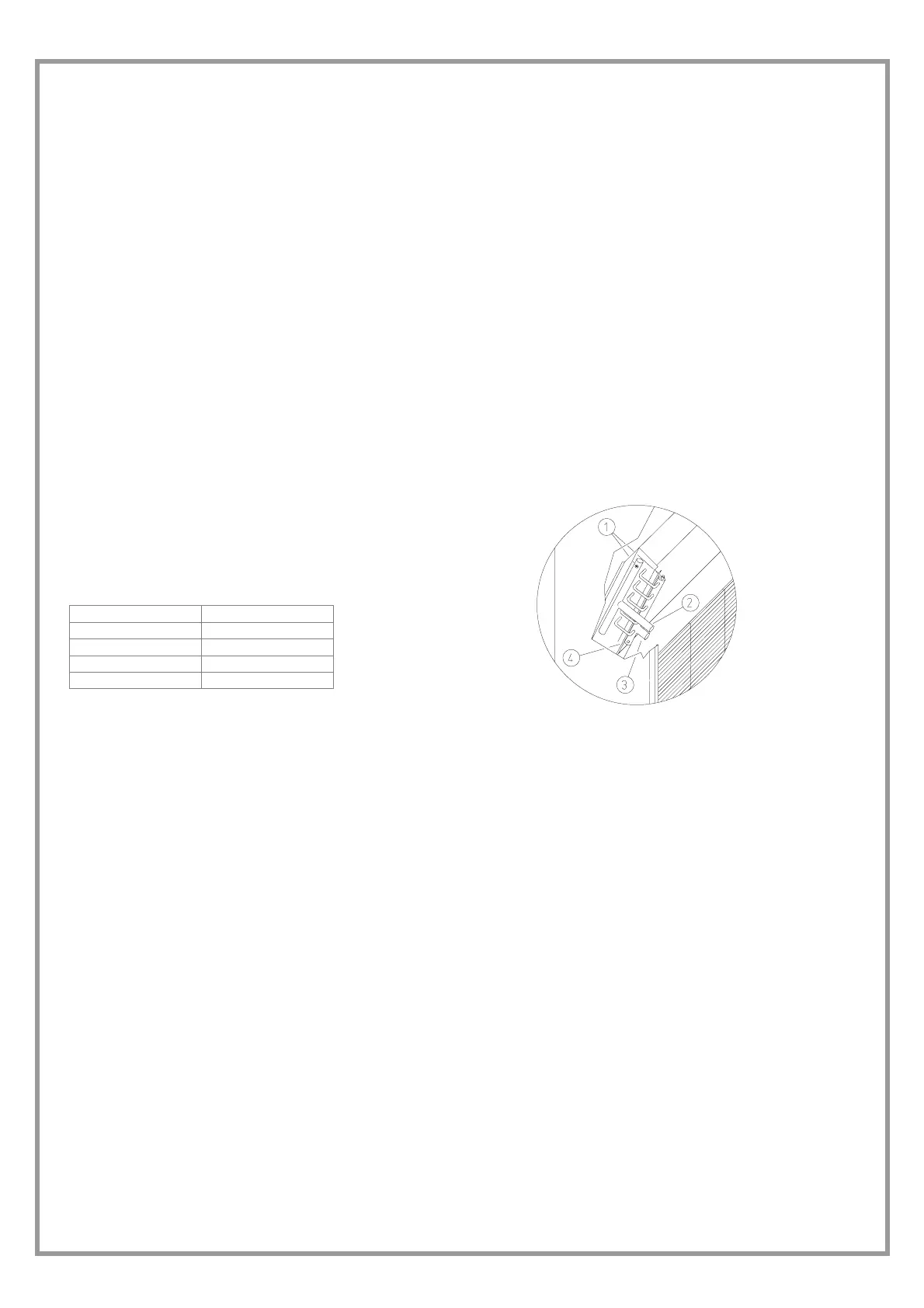
Key:
1 – Air bleed valve
2 – Water input
3 – Water supply
4 – Discharge valve
WATER CONNECTIONS
Sizes
∅
∅∅
∅ GAS
31-41-51-71 1”
91-101-121 1” ¼
142-182 1” ½
202-242 2”
 Loading...