No_
I
2
3
4
5
6
7
8
i0
l|
12
13
!4
t5
16
!7
18
19
2O
21
22
23
24
25
26
27
28
29
30
31
32
33
34
35
36
37
38
39
40
41
Oi-d_r
P_rt: No_
18619
4 {230
41716
_X-309
4{628
_X-4 i 7
41260
X437
412!4
41215
X,746
41150
38416
41421
41616
41417
X-606
X-432
41813
x-!o0
41625
41220
_X-383
41213
41718
38716
41711
41624
38812
18232
41130
41416
X-162
_X-420
'_X-377
41621
41130
)(-745
41414
X-736
X-607
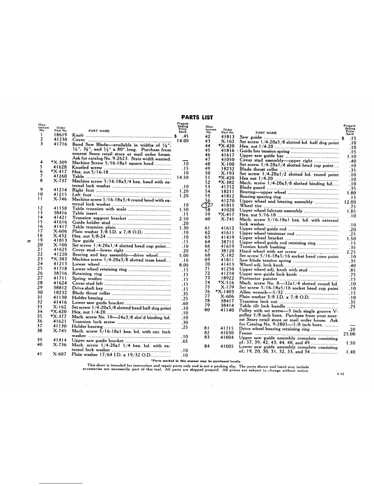
PARTS LIST
SsUfn*
PART NAME _eh
Knob ............................................................ ............ $ ,45
Cover ................................................... ........ 14.00
Band Saw Blade---avai|able in widths of l./S"+
I/_" 3,_" and ½" x 80" long_ Purchase from
nearest Sears retail store or mail order house.
Ask for catalog No. 9-262 $, State width wanted.
Machine _rew 5/16+ 18x1 square head .............. 10
Knurhd s_:rew ................................... _....................... ! 5
H_, nut 5/16-18 ...................................................... |0
Table .................................................................... {4.50
llt_t*
tl+atlorl Order
No. Part No,
42 41813
43 X.162
44 *X-420
45 41816
46 41617
47 41050
48 X.100
49 18232
50 )(-193
5 ! _X-420
52 *X-382
53 41712
54 18211
55 41812
56 41270
_8 41815
41020
59 _X-417
60 X-745
Machine screw 5/16-! 8x3/4 hew head _th _-
temal !ock washer .................................................. 10
Right foot ...........................................................1.20
_ft foot .............................................................. t.20
Machine screw 5/16-1 8x3/4 round head with ex-
ternal lock washer ............................................. 10
Table trunnion with scale ....................................... 1.50
Table inert .....................................................................15
Trunnion support bracket ...................................... 2.50
Guide: holder stud ................................................. 20
Table trunnion plain ............................................ !.30 6! 41612
Plain w_her 3/8 I.D. x 7/80.D ......................10 62 41611
Hex, nut: 3/8-24 ................................................... 10 63 41419
Saw _ide .................................................................. 15 64 38715
Set screw 1/4-20xl/4 slotted head cup point ...... 10 66 41619
Cover stud_lower fight ................................... 20 67 38120
Bearing and key assembly_rive wheel .......... 5.00 68 X-182
Machine _rew 1/4_20x3/8 slotted truss head ...... 10 69 4 | 811
Lower wheel .............................................................. 8,00 70 41413
Lower wheel retaining ring .................................. 15 71 41250
Retaining ring ................................................. 15 72 41210
Spring washer .! 5 7 3 18922
........................................................ 74 *X-516
Cover stud left .......................................................... l 5 75 X- 179
Drive shaft key ...................................................... 15 76 *X-1403
Blade thrust roller ................................................. 35 77 X-606
Holder beating ........................................................... 25 78 384 {7
Lower _w guide bracket .................................... 60 79 384{4
Set screw 1/4-20x5/8 slotted head half dog point ,10 80 41140
Hex. nut 1/4-20, ................................................... 10
Much, _rew No, ! _24x3/8 slot'd binding hd, , I 0
%unnion l_k screw ........................................ 30
Holder bearing ...................................................... 25 81 41715
Ms&, _rew 5/|6-18x! hew hd. with ext. lock 82 41030
washer ................................................................... 10 83 41004
Upper s_w guide bracket ....................................65
Much. _rew 1/4-20x I l hex. hd. with ex- 84 4 i 005
ternal !ock washer .....................................................! 0
Plain washer 17/64 I.D, x 19/32 O,D ................ 10
S,_llinS
Prt_s
PART NAME _h
Saw guide ...................................................... $ .15
Set screw I !4-20x518 slotted hd. half dog point , !0
H_ nut 1/4_20 ...............................................10
" Guide bar tension spring .......................................... l 5
Upper mW _ide bar .............................................1. I 0
_ver stud a_embly--upper right .......................40
Set screw 1/4-20x!/4 slotted head cup point ...... 10
Blade thrust roller ..................................................35
Set _r_ 1/4-20xl/2 slotted hd. round point .10
Hex nut l/4-20 ..................................................10
Much, screw 1/4-20x3/8 slotted binding hd ........ 10
Blade guard 35
Bearing---upper wheel I_80
Beating spacing ring =........................................... 15
Upper Wheel and beafing assembly ...................i2.00
_'heel tire ........................................................ 75
Upper wheel fulcrum assembly ..........................1,85
Hex, nut 5/!6-18 10
Much. screw 5/16.18x1 hex, hd. with external
lock washer ........................................................ 10
Upper wheel guide rod .......................................20
Upper wh_l ten_oner rod ...................................25
Upper wheel bracket ........................................1.50
Upper wheel guide rod retaining ring ............ 15
Tension knob bushing ..2.o.._+.......................35
Hand wheel with set screw ................. _............. 2.25
_t screw 5116-18x5116 socket head cone point +10
_w blade tension spring .......................... 35
Wh_l adj, lock knob 40
Upper wheel adL knob with stud .................. 85
Upper saw _ide lock knob ...................................75
Protractor pointer ............................................. ! 5
Much. screw No. _32x I/4 slotted round hd. oI 0
Set screw 5/16-|8x5/16 socket head cup point _10
Allen v,_ench_5i32 ..........................................15
Plain washer 3/8 LD, x 7/80.D .........................!0
Trunnion lock nut. ................................................35
Table ti!t lock handle ..........................................75
Pulley _th set screw_5 inch single groove V-
pulley 5/8 in_ bore. Purchase from your n_r-
_t _ars re_ii store or mail order house, Ask
for Catalog No. 9-2805_5/8 inch hare, ...........
Driva wheel bearing retaining ring .................20
Frame ......................................................25.00
Upper _w guide assembly complete consisting
of: 37, 39, 42, 43, 44, 48, and 49. .....................1.50
Lower saw guide a_embiy complete consisting
of; t9, 20, 30, 3t, 32, 33, and 34 .................... 1.40
35Z
 Loading...