assembly
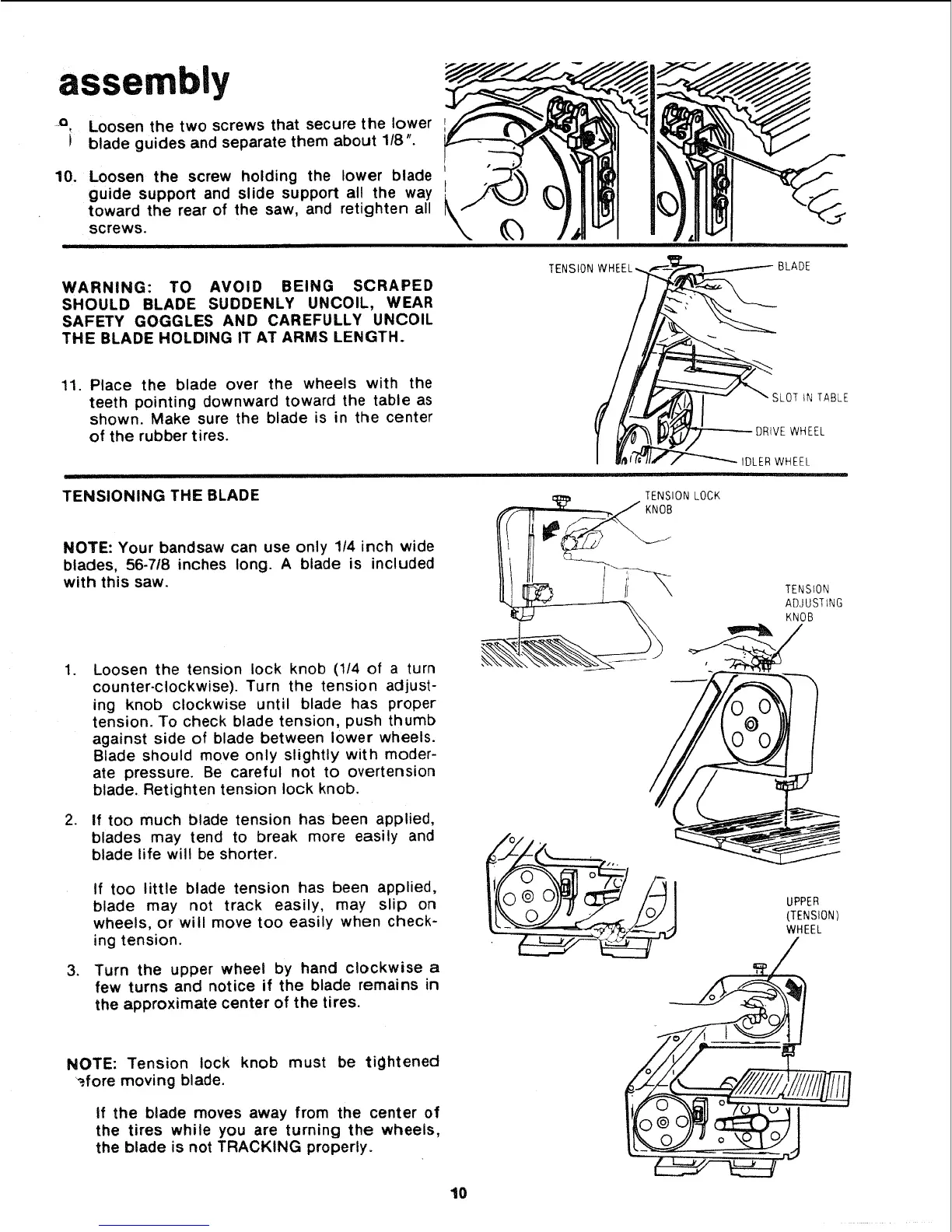
o Loosen the two screws that secure the lower
i blade guides and separate them about 1/8".
10. Loosen the screw holding the lower blade
guide support and slide support all the way L
toward the rear of the saw, and retighten all
\screws.
i
WARNING: TO AVOID BEING SCRAPED
SHOULD BLADE SUDDENLY UNCOIL, WEAR
SAFETY GOGGLES AND CAREFULLY UNCOIL
THE BLADE HOLDING IT AT ARMS LENGTH.
BLADE
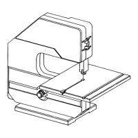
11. Place the blade over the wheels with the
teeth pointing downward toward the table as
shown. Make sure the blade is in the center
of the rubber tires.
SLOT iN TABLE
)RIVE WHEEL
IDLER WHEEL
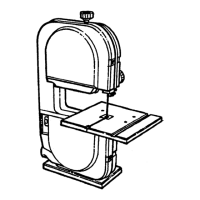
TENSIONING THE BLADE
TENSION LOCK
KNOB
NOTE: Your bandsaw can use only 114 inch wide
blades, 56-718 inches long. A blade is included
with this saw.
.
.
,
Loosen the tension lock knob (1/4 of a turn
counter-clockwise). Turn the tension adjust-
ing knob clockwise until blade has proper
tension. To check blade tension, push thumb
against side of blade between lower wheels.
Blade should move only slightly with moder-
ate pressure. Be careful not to overtension
blade. Retighten tension lock knob.
If too much blade tension has been applied,
blades may tend to break more easily and
blade life will be shorter.
If too little blade tension has been applied,
blade may not track easily, may slip on
wheels, or will move too easily when check-
ing tension.
Turn the upper wheel by hand clockwise a
few turns and notice if the blade remains in
the approximate center of the tires.
NOTE: Tension lock knob must be tightened
_.fore moving blade.
if the blade moves away from the center of
the tires while you are turning the wheels,
the blade is not TRACKING properly.
10
TENSION
ADJUSTING
KNOB
 Loading...