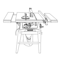
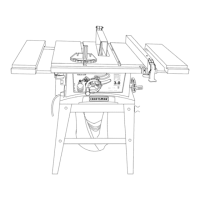
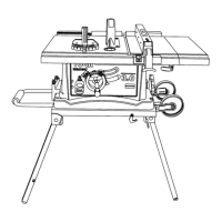
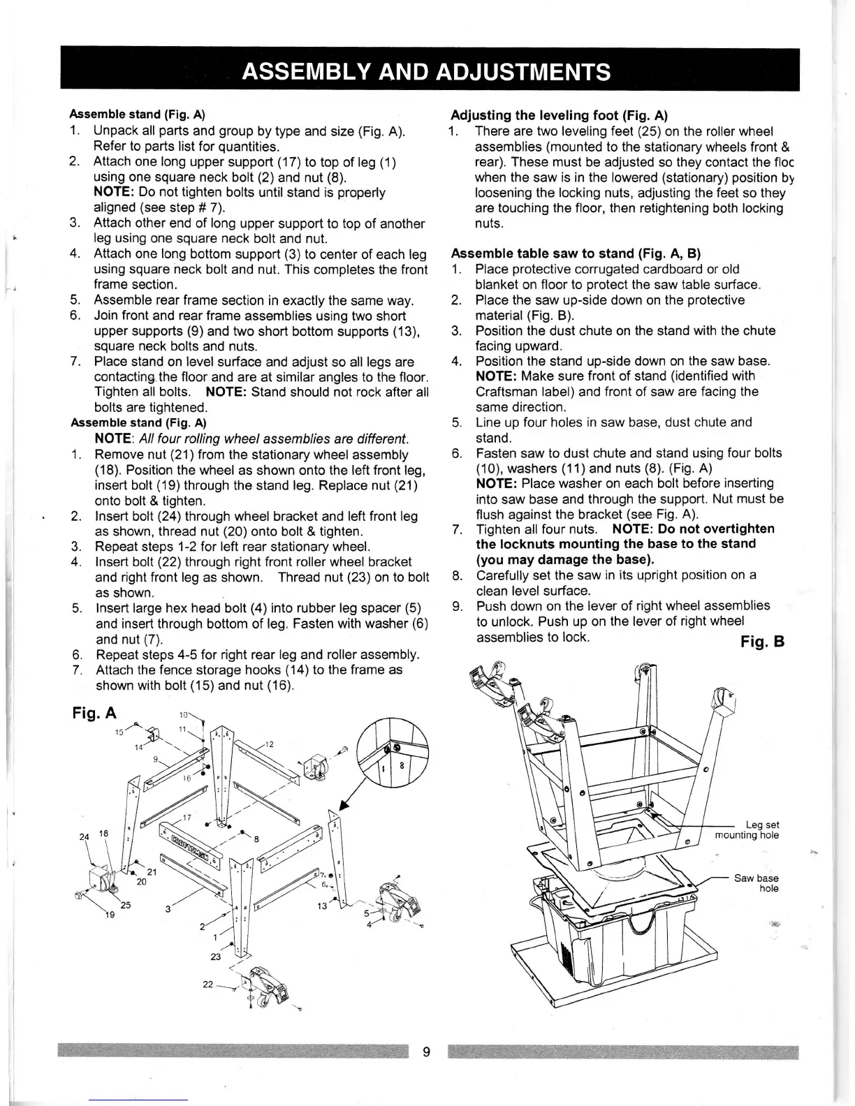
Assemble
stand
(Fig.
A)
1.
Unpack
all
parts
and
group
by type and
size
(Fig.
A).
Refer to
parts
list
for
quantities.
2. Attach
one long
upper
support
(17)to
top of
leg
(1)
using
one square
neck
bolt
(2)
and nut
(8).
NOTE: Do not
tighten
bolts until
stand
is
properly
aligned
(see
step
#
7).
3.
Attach
other end
of
long
upper
support to
top
of another
leg using
one square neck
bolt
and
nut.
4.
Attach
one
long
bottom
support
(3)
to
center of each leg
using square neck
bolt and nut. This
completes the front
frame section.
5. Assemble
rear frame
section in
exactly
the
same
way.
6. Join front
and rear frame
assemblies using two
short
upper
supports
(9)
and two short bottom
supports
(13),
square neck bolts
and nuts.
7.
Place
stand on level
surface and adjust
so
all legs are
contacting the
floor and
are at similar angles to the floor.
Tighten
all bolts. NOTE:
Stand
should
not
rock
after all
bolts are tightened.
Assemble stand
(Fig.
A)
NOTE:
Allfour rolling wheel assemblies
are
different.
1.
Remove nut
(21)
from the stationary wheel
assembly
(18).
Position
the wheel
as
shown onto the left front leg,
insert bolt
('19)through
the stand leg. Replace nut
(21)
onto bolt & tighten.
2. lnsert bolt
(24)through
wheel bracket and left front leg
as
shown,
thread nut
(20)onto
bolt & tighten.
Repeat steps 1-2 for left rear stationary wheel.
lnsert bolt
(22)
through right front roller wheel
bracket
and right front leg
as
shown. Thread nut
(23)
on
to
bolt
as
shown.
lnsert large hex head bolt
(4)
into rubber leg spacer
(5)
and insert
through bottom of
leg. Fasten with
washer
(6)
and nut
(7).
Repeat steps
4-5
for
right
rear
leg and roller assembly.
Attach the fence
storage
hooks
(14)to
the frame as
shown
with
bolt
(15)and
nut
(16).
Adjusting
the
leveling
foot
(Fig.
A)
1. There
are two leveling feet
(25)
on
the roller
wheel
assemblies
(mounted
to the
stationary wheels front &
rear). These must be
adjusted so they contact the floc
when the
saw is
in the
lowered
(stationary)
position
by
loosening
the locking
nuts, adjusting the feet
so
they
are
touching
the floor, then retightening both locking
nuts.
Assemble
table saw
to
stand
(Fig.
A,
B)
1. Place
protective
corrugated
cardboard or old
blanket on
floor to
protect
the
saw
table surface.
2. Place the saw up-side down on
the
protective
material(Fig. B).
3. Position the dust chute on
the
stand
with the
chute
facing upward.
4. Position
the
stand up-side down
on the saw base.
NOTE: Make sure
front of stand
(identified
with
Craftsman
label) and front of saw are facing
the
same direction.
5.
Line up four holes
in
saw base,
dust chute and
stand.
6. Fasten saw
to
dust
chute and stand
using four
bolts
(10),
washers
(1
1) and
nuts
(8). (Fig.
A)
NOTE:
Place washer on each bolt
before inserting
into saw base and
through
the
support.
Nut must
be
flush
against the bracket
(see
Fig. A).
7. Tighten all
four nuts. NOTE:
Do not overtighten
the
locknuts mounting the base
to the stand
(you
may damage
the base).
8. Carefully
set the saw
in its upright
position
on a
clean
level surface.
L Push
down on
the lever of
right wheel assemblies
to
unlock. Push
up on the lever
of right
wheel
assemblies
to lock.
Fig.
B
Leg set
mounting
hole
3.
4.
5.
6.
7.
Fig. A
_^_
-
t5'
a
tl'
21
'\.R.
"-*+-m-.
ASSEMBLY
AND
ADJUSTMENTS
e-
ry
 Loading...