7
ASSEMBLY
Set-Up
NOTE: Remove the deck wash system nozzle adapter and oil drain tube from the
manual bag and store for future use.
Moving The Riding Mower Manually
Your riding mower’s transmission is equipped with a hydrostatic relief valve for
occasions when it is necessary to move the riding mower manually. Opening this
valve permits the fluid in the transmission to bypass its normal route, allowing the
rear tires to “freewheel.” To open the hydrostatic relief valve, proceed as follows:
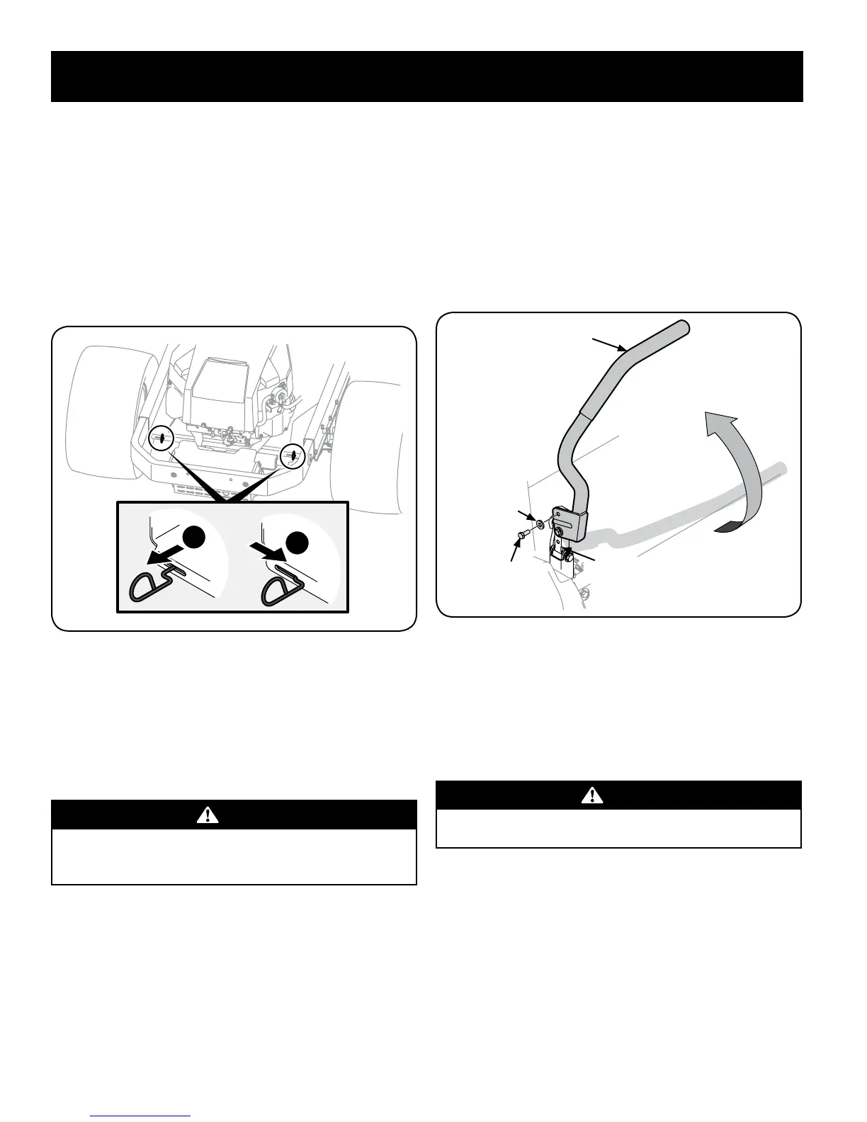
1. Locate the hydrostatic bypass rod in the rear of the riding mower. See “Figure
1”.
Figure 1
2. Engage the bypass rods by pulling each one out (a) and to the right (b) to
lock it into place. See “Figure 1”.
3. Disengage the bypass rods by reversing steps a & b after moving the tractor.
See “Figure 1”.
NOTE: The transmission will NOT engage when the hydrostatic bypass rod is
pulled out. Return the rod to its normal position prior to operating the riding
mower.
CAUTION
Never attempt to move the riding mower manually without first opening
the hydrostatic relief valve. Doing so will result in serious damage to the
riding mower’s transmission.
Position Drive Control levers
The drive control levers of the riding mower are lowered for shipping purposes.
The flange lock nuts, hex screws, and flat washers that normally secure the control
levers in their operating position are unfastened and installed in the slotted holes of
the control levers for shipment. The control levers must be repositioned to operate
the riding mower. To reposition the control levers for operation, proceed as follows:
1. Remove the hex screws and flat washers from the hardware pack in your
manual bag.
2. Lift and swing that control lever upward until the slotted hole in the lever
bracket aligns with one of the holes in the pivot bracket. See “Figure 2”.
Control Lever
Hex Screw
Pivot
Bracket
Flat Washer
Lift Control
Lever Upward
Figure 2
3. Slide the flat washer onto the hex screw. From the outside, insert the hex
screw with washer through the control lever slot and the hole of the pivot
bracket. See “Figure 2”. Using a 1⁄2” wrench snug the screw, but do not fully
tighten.
4. Note the relative position of the control lever to the pivot bracket,
then repeat the previous steps to reposition the other control lever in
approximately the same position.
CAUTION
Torque the screws down tightly to prevent the control levers from slipping
out of position.
5. Refer to “Adjusting the Drive Control Levers” in the Maintenance &
Adjustments for instructions on the final adjustment of the levers.
 Loading...