Assembly
9
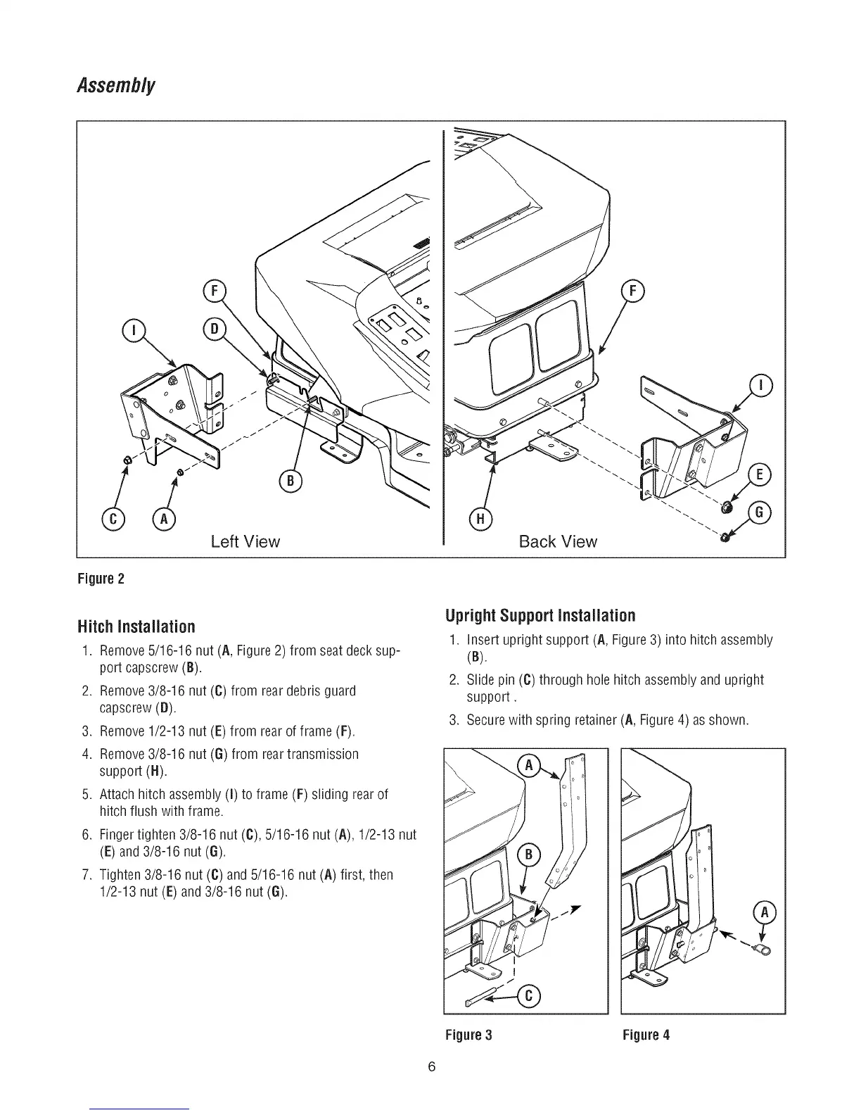
Back View
Figure2
HitchInstallation
1. Remove5/16-16 nut (A, Figure 2) from seat deck sup-
port capscrew (B).
2. Remove3/8-16 nut (C) from reardebris guard
capscrew(D).
3. Remove1/2-13 nut (E) from rear of frame (F).
4. Remove3/8-16 nut (G) from rear transmission
support (H).
5. Attach hitch assembly (I) to frame (F) sliding rear of
hitch flush with frame.
6. Fingertighten 3/8-16 nut (C), 5/16-16 nut (A), 1/2-13 nut
(E) and 3/8-16 nut (6).
7. Tighten 3/8-16 nut (C)and 5/16-16 nut (A) first, then
1/2-13 nut (E) and3/8-16 nut (6).
UprightSupport Installation
1. insert upright support (A, Figure 3) into hitch assembly
(B).
2. Slide pin (C) through hole hitch assemblyand upright
support.
3. Secure with spring retainer (A, Figure4) asshown.
J
Figure 3 Figure 4

 Loading...