DO GUIDE
DOC. 7868A (2046973) 09.16
Specications subject to change without notice.
Mounting onto a Flat Surface
1. Install the wall mount brackets with three at head screws (included) per side.
2. Secure the amplier to a at surface using four mounting screws (not included),
Placing onto a Flat Surface
Attach the included feet to place the amplier(s) on a at surface.
DO Connect the Device
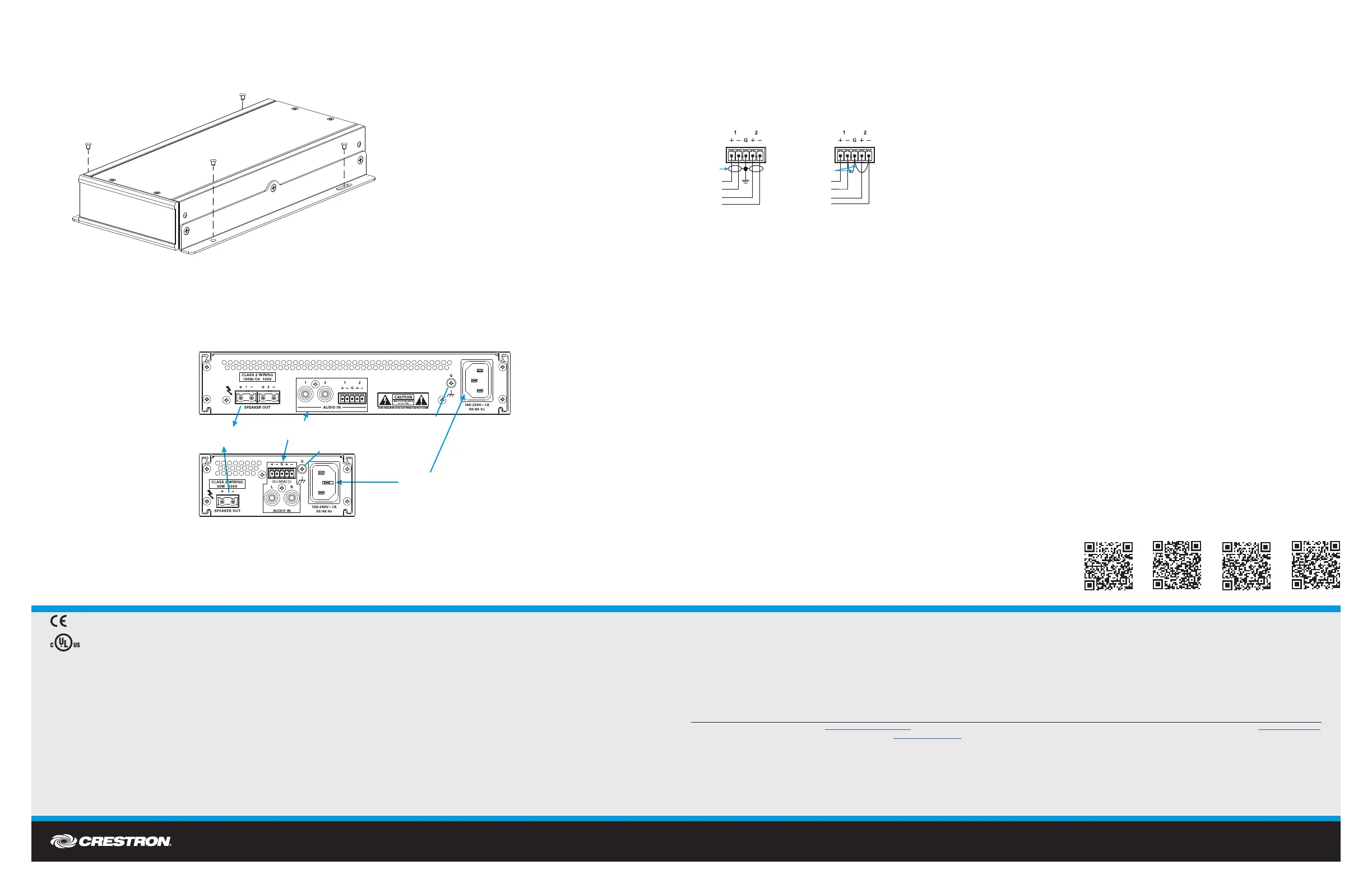
Make the necessary connections as called out in the following diagrams. Connect power last.
CAUTION: Keep the device unplugged until all of the input and speaker wiring is complete.
CAUTION: Check the speaker wires for shorts and frayed wiring around the SPEAKER OUT connectors.
NOTE: On the AMP-150 and AMP-1200, the left and right inputs are summed to the amplier’s output.
NOTE: Ensure the unit is properly grounded by connecting the chassis ground lug to an earth ground (building steel).
NOTE: To prevent overheating, do not operate this product in an area that exceeds the environmental temperature range listed in the table of
specications.
When connecting an input signal, use either the RCA connection or the 5-pin terminal block connector. The 5-pin terminal block connector can be
connected to balanced and unbalanced sources. Refer to the following diagrams for connecting a source.
DO Operate the Device
Apply Power
To turn the amplier and audio outputs on, connect the supplied power cord to the power connector on the rear of the amplier.
LED Operation
When power is applied to the device, the PWR LED on the front panel operates with the following behavior:
• Green - Normal operation
• Amber - Sleep operation
The SIGNAL LED provides the following information about the audio signal:
• Green - An audio signal is present.
• Red - The audio signal is clipped.
The FAULT LED indicates a fault on the indicated channel.
Adjust the Signal Levels
WARNING: This amplier is capable of delivering high power to the loudspeakers. Please use caution and adequate ear protection if listening to content
at high volume levels as continued exposure to high sound pressure levels can cause permanent hearing impairment or loss.
Each input has its own signal level control that can be adjusted as necessary to balance the sound between inputs or to accommodate different audio
sources. To adjust an input’s level, use a Philips screwdriver to turn the knob clockwise to increase the signal level or counterclockwise to reduce the
signal level.
As of the date of manufacture, the product has been tested and found to comply with specications for CE marking.
These products are Listed to applicable UL Standards and requirements by Underwriters Laboratories Inc.
Ces produits sont énumérés aux normes applicables et les exigences UL par Underwriters Laboratories Inc.
Federal Communications Commission (FCC) Compliance Statement
This device complies with part 15 of the FCC Rules. Operation is subject to the following two conditions:
(1) This device may not cause harmful interference, and (2) this device must accept any interference received, including interference that may cause undesired operation.
CAUTION: Changes or modications not expressly approved by the manufacturer responsible for compliance could void the user’s authority to operate the equipment.
NOTE: This equipment has been tested and found to comply with the limits for a Class B digital device, pursuant to part 15 of the FCC Rules. These limits are designed to provide reasonable protection
against harmful interference in a residential installation. This equipment generates, uses and can radiate radio frequency energy and, if not installed and used in accordance with the instructions, may
cause harmful interference to radio communications. However, there is no guarantee that interference will not occur in a particular installation.
If this equipment does cause harmful interference to radio or television reception, which can be determined by turning the equipment off and on, the user is encouraged to try to correct the interference
by one or more of the following measures:
• Reorient or relocate the receiving antenna.
• Increase the separation between the equipment and receiver.
• Connect the equipment into an outlet on a circuit different from that to which the receiver is connected.
• Consult the dealer or an experienced radio/TV technician for help.
Industry Canada (IC) Compliance Statement
CAN ICES-3(B)/NMB-3(B)
Rack Mounting Safety Precautions
• Elevated Operating Ambient Temperature: If installed in a closed or multi-unit rack assembly, the operating ambient temperature of the rack environment may be greater than room ambient temperature. Therefore, consideration should be
given to installing the equipment in an environment compatible with the maximum ambient temperature (Tma) specied by the manufacturer.
• Reduced Airow: Installation of the equipment in a rack should be such that the amount of airow required for safe operation of the equipment is not compromised.
• Mechanical Loading: Mounting of the equipment in the rack should be such that a hazardous condition is not achieved due to uneven mechanical loading.
• Circuit Overloading: Consideration should be given to the connection of the equipment to the supply circuit and the effect that overloading of the circuits might have on overcurrent protection and supply wiring. Appropriate consideration
of equipment nameplate ratings should be used when addressing this concern.
• Reliable Earthing: Reliable earthing of rack-mounted equipment should be maintained. Particular attention should be given to supply connections other than direct connections to the branch circuit (e.g., use of power strips).
Electrical Connection
“This product must be connected to an earthed mains socket-outlet.”
• Finland: “Laite on liitettävä suojamaadoituskoskettimilla varustettuun pistorasiaan.”
• Norway: “Apparatet må tilkoples jordet stikkontakt.”
• Sweden: “Apparaten skall anslutas till jordat uttag.”
The specic patents that cover Crestron products are listed at http://www.crestron.com/legal/patents. The product warranty can be found at www.crestron.com/warranty.
Certain Crestron products contain open source software. For specic information, please visit www.crestron.com/opensource.
Crestron and the Crestron logo are either trademarks or registered trademarks of Crestron Electronics, Inc., in the United States and/or other countries. Other trademarks, registered trademarks, and trade names may be used in this document to refer to either the entities claiming the marks and
names or their products. Crestron disclaims any proprietary interest in the marks and names of others. Crestron is not responsible for errors in typography or photography.
This document was written by the Technical Publications department at Crestron.
©2016 Crestron Electronics, Inc.
DO Learn More
Visit the website for additional information and the latest rmware
update. To learn more about this product, use a QR reader application
on your mobile device to scan the QR images.
Crestron Electronics
15 Volvo Drive, Rockleigh, NJ 07647
888.CRESTRON | www.crestron.com
AUDIO IN:
From audio source
POWER:
From line voltage
Ground
Ground
SPEAKER OUT:
To speaker(s)
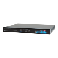
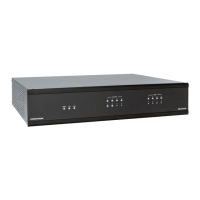
AMP-2100-100, AMP-2100-70,
AMP-2100, AMP-1200-100,
AMP-1200-70 (AMP-2100-100 shown)
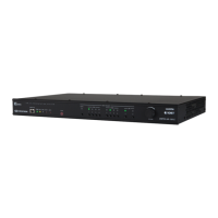
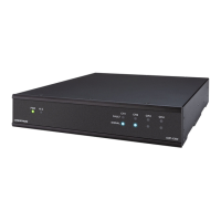
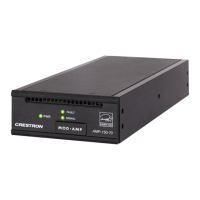
AMP-225, AMP-150-100,
AMP-150-70 (AMP-150-100 shown)
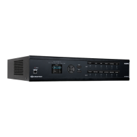
A M P-150
A M P-12 00
AMP-2100
Wiring for Balanced Input
Left
Shield
Wiring for Unbalance
+
+
Right
Left
Jumpers
+
+
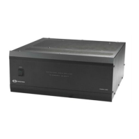
AMP-225
 Loading...