DO GUIDE
DOC. 8216A (2049453) 12.17
Specications subject to change without notice.
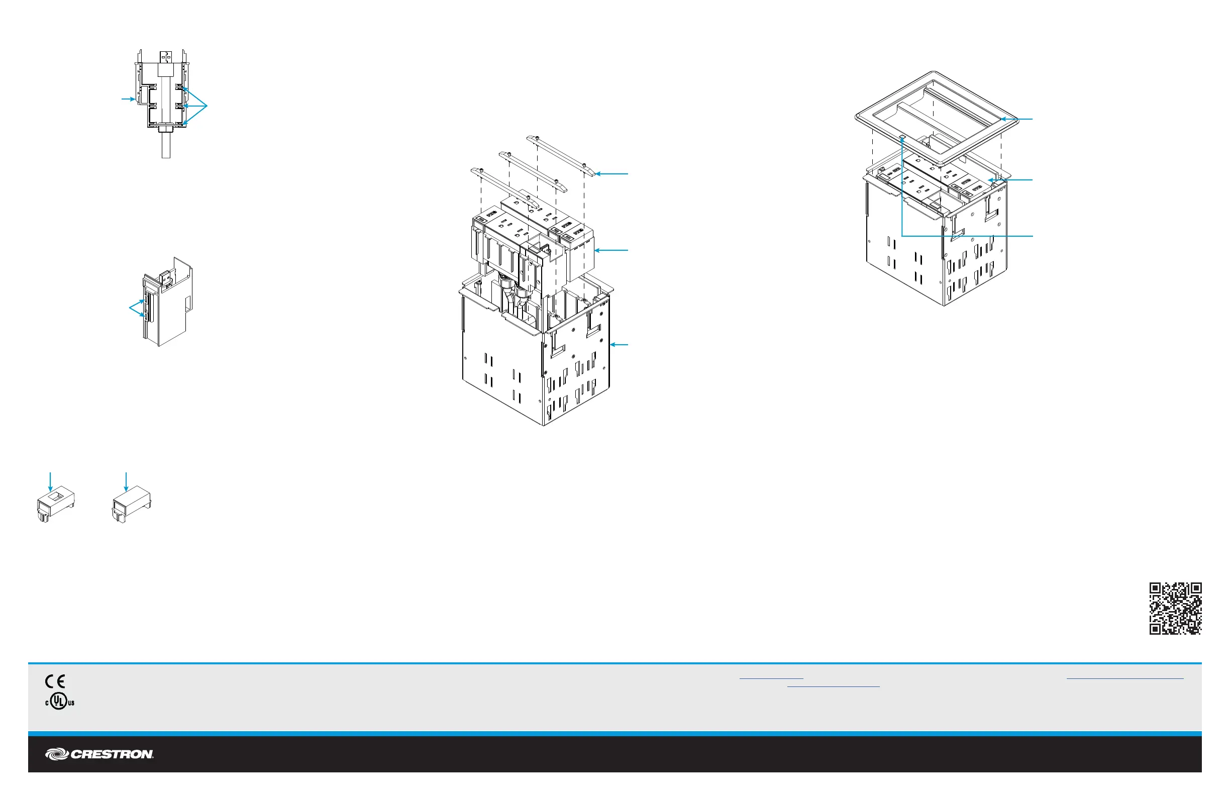
3. Place the cable plate in one of the three locations shown in the illustration below so that the top
of the cable connector is ush with the top of the module.
NOTE: The cable connector must not extend beyond the top of the module.
4. Attach the side plate to the module by snapping the plastic clips on the plate into the two slots
on the module.
NOTE: Ensure that the cable is properly installed in the module prior to attaching the side
plate, as the plate is difcult to remove once it is attached. If the side plate needs to be
removed, use a small, at object (such as a at-head screwdriver) to carefully pry the plastic
clips on the side plate off of the module near the two slots. Refer to the following illustration.
5. Feed the other end of the cable through an empty module space in the FT2-MECH assembly.
6. Push the top of the module down into the empty module space in the FT2-MECH assembly so
that the module slides into place. Use the guide ribs on the front and rear of each module to
help position the module in the assembly.
Installing Blank and Keystone Plates
Blank plates ll empty spaces in a module row, while keystone plates allow for cables terminated with
standard keystone jacks to be installed in the FlipTop system. Both plates require one empty space in a
module row for installation.
To install the blank or keystone plates, push the plates down into the appropriate module spaces in the
FT2-MECH assembly so that the plate slides into place. Use the guide ribs on the front and rear of each
plate to help position the plate in the assembly. For keystone plates, snap the cable’s keystone jack into
the keystone opening in the plate, and then feed the cable down through the empty module space before
installing the plate.
DO Complete the Installation
1. Once the modules and blank plates are installed and level with their surroundings, place the
locking bars into position so that the screws on each side of the locking bars engage the
screw holes on the assembly. Then, hand tighten the two screws on each bar until the bars are
secured to the assembly.
CAUTION: To avoid stripping the screws on the locking bars, hand tighten the screws using a
manual screwdriver only.
NOTE: Ensure that each module space in the row is lled with a module or a blank plate
before installing the locking bars.
2. Hold the magnetic bezel over the assembly so that the lid retraction button on the bezel is
aligned with the front of the assembly. Then, lower the bezel onto the assembly so that the
retractable lid ts into the rear opening in the bezel and the magnets snap into place against
the assembly.
As of the date of manufacture, the product has been tested and found to comply with specications for CE marking.
This product is Listed to applicable UL
®
Standards and requirements tested by Underwriters Laboratories Inc.
Ce produit est homologué selon les normes et les exigences UL applicables par Underwriters Laboratories Inc.
The specic patents that cover Crestron products are listed at www.crestron.com/legal/patents. The product warranty can be found at www.crestron.com/legal/sales-terms-conditions-warranties.
Certain Crestron products contain open source software. For specic information, visit www.crestron.com/legal/open-source-software.
Crestron, the Crestron logo, and FlipTop are either trademarks or registered trademarks of Crestron Electronics, Inc., in the United States and/or other countries. UL and the UL logo are either trademarks or registered trademarks of Underwriters Laboratories, Inc., in the United States and/or
other countries. Other trademarks, registered trademarks, and trade names may be used in this document to refer to either the entities claiming the marks and names or their products. Crestron disclaims any proprietary interest in the marks and names of others. Crestron is not responsible for
errors in typography or photography.
This document was written by the Technical Publications department at Crestron.
©2017 Crestron Electronics, Inc.
DO Learn More
Visit the website for additional information and the latest rmware updates. To learn more
about this product, use a QR reader application on your mobile device to scan the QR
image.
Crestron Electronics
15 Volvo Drive, Rockleigh, NJ 07647
888.CRESTRON | www.crestron.com
Blank plateKeystone plate
FT2-MECH
assembly
FT2A modules
Retractable lid
ts inside this
opening in bezel
Retractable lid
Lid retraction
button
Pry plastic clips
from slots on
cable management
module
Cable plate with
nylon grommet
can be installed
in these three slots
Pass-through
module (with side
plate removed)
 Loading...