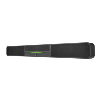
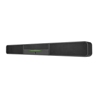
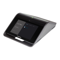
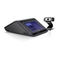
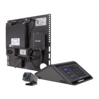
Crestron® UC Video Conference Smart Sound Bars (UC-SB1 and UC-SB1-CAM) facilitate conferencing in small to medium-sized meeting spaces
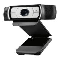
with a built-in microphone, speakers, and camera (UC-SB1-CAM only).
NOTE: With the exception of the integrated camera, the UC-SB1 and UC-SB1-CAM have similar features. For simplicity within this guide, the term
“sound bar” is used for both models except where noted.
Check the Box
Item Qty
UC-SB1 and UC-SB1-CAM 1
Anchor, Drywall, Plastic, 3/8 in. x 1/2 in. (P/N 2052565) 4
Cable, USB 3.0, A - B, 6 ft (1.83 m) (P/N 2053077) 1
Foot, 2.3 in. x 0.96 in. x 0.15 in., Rubber (P/N 2052169) 2
Key, Anchor (P/N 4529654) 1
Power Cord (P/N 2052498) 1
Screw, 8-AB x 1-1/2 in., Pan Head, Combo (P/N 2052567) 4
Template, Overlay (P/N 4529513) 1
Install the Sound Bar
The sound bar can be placed on a flat surface or mounted on a wall. The sound bar has the following dimensions:
Dimensions (UC-SB1-CAM shown)
43.60 in.
(1107 mm)
4.57 in.
(116 mm)
3.90 in.
(99 mm)
Place on a Flat Surface
If placing the sound bar on a flat surface, attach the included rubber feet to the bottom of the sound bar as shown in the following diagram.
Attach Rubber Feet (UC-SB1 shown)
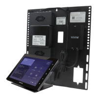
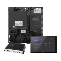
Mount on a Wall
The sound bar includes anchors that are suitable for use on sheetrock walls up to 1/2 in. thickness. Masonry and other materials may require
additional installer-supplied mounting hardware.
NOTE: When mounting on a wall beneath a display device, leave 3/4 in. (minimum) clearance above the top of the sound bar. Use the included
template to allow for sufficient clearance between the sound bar and display device.
The following tools are required to mount the sound bar:
• Drywall saw (not included)
• Drill with 5/16 in. bit (not included)
To mount the sound bar on a wall:
1. The included template provides drill hole locations for the wall mount hardware. Using the center reference hole of the template as a guide,
attach the template to the desired mounting location with the center reference line of the template at the center of the desired location.
NOTE: The cutout in the center of the template should provide adequate access for all of the required cabling.
Drill one of these two holes
Drill one of these two holes Cutout for sound bar cables
Drill one of these two holes
Drill one of these two holes
2. Drill two pilot holes on each side of the center line as shown in the diagram above. Each side should have one pilot hole drilled in each row of
the template.
3. Use a drywall saw to make a cutout for the sound bar cables.
4. Install the four included anchors into the drilled pilot holes.
a. Fold the anchor in the middle and pinch the ends together.
b. Insert the anchor in the hole and tap flush with the wall.
c. Insert the included anchor key to pop the anchor open and lock
it behind a hollow wall.
WARNING: Do not force or hammer the key.
d. Drive the screw part of the way into the anchor, leaving
approximately 1/4 inch of the screw exposed.
e. Repeat steps a through d for the other 3 anchors.
UC-SB1 and UC-SB1-CAM
UC Video Conference Smart Sound Bars