page 7
CE Series Power Amplifiers
Operation Manual
2.4 Choose Input Wire
and Connectors
You have three choices of input connectors:
1/4-inch (6.35-mm) phone, 3-pin XLR, or
barrier strip. You can also use either balanced or
unbalanced wiring.
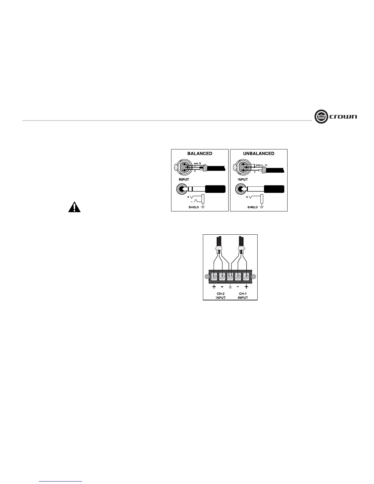
Figure 2.3 shows balanced connector pin
assignments for XLR and phone. Figure 2.4
shows unbalanced connector pin assignments
for XLR and phone.
Figure 2.5 shows barrier strip input wiring for a
balanced signal. Both channels should be wired
using a common center terminal for ground con-
nection.
NOTE: Custom wiring should only be
performed by qualified personnel.
Figure 2.3 Balanced Input
Connector Wiring
Figure 2.4 Unbalanced Input
Connector Wiring
2 Setup
Figure 2.5 Barrier Strip Input Wiring:
Balanced Signal In
 Loading...