EasyManua.ls Logo

Crown Com-Tech CT-1600 User Manual

Crown Com-Tech CT-1600
49 pages
To Next Page IconTo Next Page
To Previous Page IconTo Previous Page
Page #17 background image
Page 17
Com-Tech 200/400/800/1600 Power Amplifiers
tween the positive (+) terminals of both channels.
CAUTION: When Parallel-Mono wiring is installed, do
not attempt to operate in Dual or Bridge-Mono mode
until the wiring is removed (especially the jumper wire).
Failure to do so will result in high distortion and exces-
sive heating.
3.3.2 Input Connection
The balanced inputs have a nominal impedance of
20 K ohms (10 K ohms unbalanced) and will accept
the line-level output of most devices. The factory-in-
stalled P.I.P.-BB provides a balanced three-terminal
input barrier block for each channel (see Figure 2.2).
Optional
P.I.P.
modules like the P.I.P.-FX, P.I.P.-FXQ
and P.I.P.-FPX can provide female XLR connectors,
phone jacks and phono (RCA) connectors. Various
P.I.P.s
are also available which provide a wide range
+
INPUT
+
INPUT
2-wire line cord
(or battery power)
Note: If two or more channels with
the same input ground reference
are driven from the same
floating source, connect
only one shield to the
source chassis.
Floating
source
+
3-wire grounded line cord
(or other ground connection)
Output
Shield not connected
at this end
Grounded
source
+
Output
Fig. 3.9 Balanced Input Wiring
Sometimes large subsonic (subaudible) frequencies
are present in the input signal. These can damage
loudspeakers or step-down transformers by overload-
ing or overheating them. To attenuate such frequen-
cies, place a capacitor in series with the input signal
line. The graph in Figure 3.10 shows some capacitor
values and how they affect frequency response. Use
only low-leakage capacitors.
Another problem to avoid is large levels of radio fre-
quencies or RF in the input signal. Although high RF
levels may not pose a threat to the amplifier, they can
burn out tweeters or other loads that are sensitive to
of input signal processing features (see Section 8).
Proper input wiring depends on two factors:
(1) whether the input signals are balanced or unbal-
anced, and (2) whether the signal source floats or has
a ground reference. The following illustrations provide
examples of recommended connection techniques for
each type of signal source.
S O L V I N G I N P U T P R O B L E M S
Fig. 3.8 Unbalanced Input Wiring
+
Twin-lead shielded cable
+
INPUT
2-wire line cord
(or battery power)
Output
Floating
source
Shield connected
to ground terminal
+
INPUT
3-wire grounded line cord
(or other ground connection)
Shield not connected
at this end
Grounded
source
3-wire grounded line cord
(or other ground connection)
Input ground
terminal not used
INPUT
Grounded
source
Single-conductor coax
or twisted pair
+
Output
+
INPUT
+
2-wire line cord
(or battery power)
Output
Floating
source
Shield connected to both
negative () and ground
input terminals
+
Output
+
1 Hz 10 Hz 100 Hz 1 kHz 10 kHz
dB
0
5
10
15
1 f
µ
.1 f
µ
.05 f
.01 f
µ
µ
Frequency
Fig. 3.10 Subsonic Filter Capacitor Values

Table of Contents

Other manuals for Crown Com-Tech CT-1600

Question and Answer IconNeed help?

Do you have a question about the Crown Com-Tech CT-1600 and is the answer not in the manual?

Crown Com-Tech CT-1600 Specifications

General IconGeneral
Channels2
Frequency Response20Hz - 20kHz
THD<0.05%
Signal to Noise Ratio>100 dB
Input Sensitivity1.4V
Power Output1600W
Total Harmonic Distortion<0.05%
Input Impedance20k ohms balanced, 10k ohms unbalanced
Dimensions19" x 3.5" x 16"

Summary

Warranty Information

Worldwide Warranty

Summary of Crown warranty terms for global coverage.

North America Warranty

Summary of Crown warranty terms for North American coverage.

Fire Protective Signaling

Fire Protective Signaling Systems

UL listing and requirements for fire alarm systems.

Welcome and Introduction

Unpacking and Inspection

Procedures for unpacking and checking for shipping damage.

Amplifier Features

Key technological advancements and benefits of the amplifier.

Facilities Overview

Front Panel Facilities

Description of indicators, switches, and connectors on the front panel.

Rear Panel Controls and Connections

Description of rear panel switches, inputs, and outputs.

Installation Procedures

Mounting and Rack Installation

Guidelines for physically installing the amplifier in racks or stacks.

Cooling and Airflow Management

Importance of ventilation and methods for optimal cooling.

Wiring and Input/Output Connections

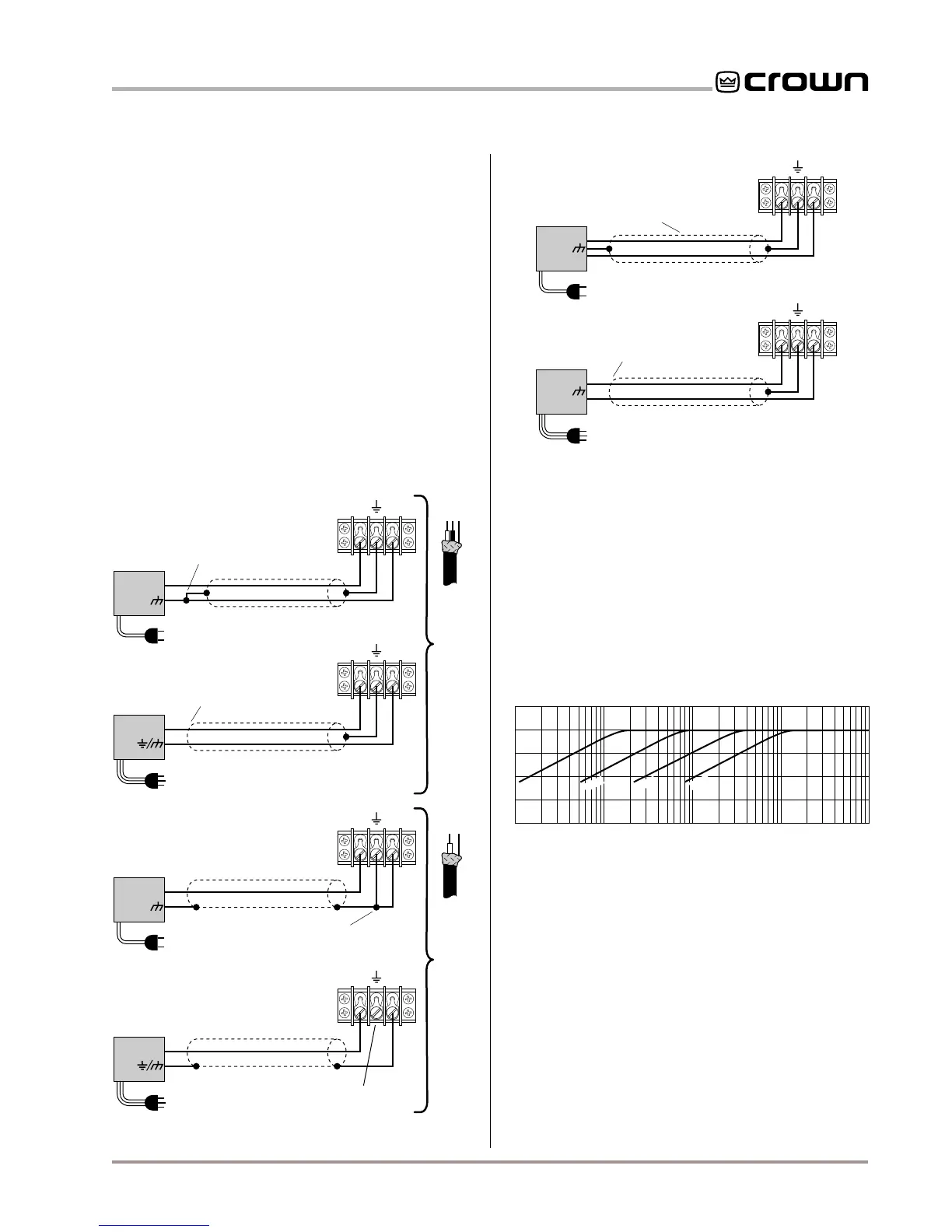
Guidance on connecting inputs, outputs, and various wiring configurations.

Input Connection Details

Details on connecting input signals and solving input problems.

Output Connection Procedures

Details on connecting output loads and using good connectors.

Additional Load Protection

Methods for protecting loudspeakers from power issues.

AC Mains Power Connection

Information on power requirements, cords, and outlets.

Operation and Controls

Operating Precautions

Essential safety and operational advice for using the amplifier.

Front Panel Indicators

Explanation of ODEP, IOC, SPI, and Enable indicator states.

Protection Systems Overview

Description of ODEP, standby, and circuit breaker protection features.

Amplifier Controls and Adjustments

Details on using level controls, sensitivity switches, and filter cleaning.

Technical Information

Amplifier Overview and Technology

Introduction to Com-Tech technology and design principles.

Circuit Theory and Operation Modes

Explanation of dual, bridge-mono, and parallel-mono circuit operation.

Specifications

Performance Characteristics

Details on frequency response, distortion, damping factor, etc.

Power Output Ratings

Guaranteed minimum power output under various conditions.

Control and Input/Output Specs

Specs for controls, indicators, input impedance, and sensitivity.

Construction and Physical Data

Information on build, dimensions, weight, and cooling design.

Power Matrices

Minimum Guaranteed Power

Detailed power output tables for Com-Tech 200.

Com-Tech 400 Minimum Power Matrix

Detailed power output tables for Com-Tech 400.

Com-Tech 800 Minimum Power Matrix

Detailed power output tables for Com-Tech 800.

Com-Tech 1600 Minimum Power Matrix

Detailed power output tables for Com-Tech 1600.

Maximum Power Specifications

Tables showing maximum power output under burst conditions.

Com-Tech 200 Maximum Power Matrix

Maximum power output tables for CT200 under burst.

Com-Tech 400 Maximum Power Matrix

Maximum power output tables for CT400 under burst.

Com-Tech 800 Maximum Power Matrix

Maximum power output tables for CT800 under burst.

Com-Tech 1600 Maximum Power Matrix

Maximum power output tables for CT1600 under burst.

Performance Graphs

Frequency Response and Damping Factor

Graphs showing amplifier frequency response and damping factor.

Phase Response and Crosstalk

Graphs detailing phase response and channel crosstalk.

AC Power Draw and Thermal Dissipation

Accessories

P.I.P. Modules Overview

Introduction to Programmable Input Processor modules and their functions.

Cooling Fan Option

Details and installation for the optional cooling fan kit.

Constant Voltage Computer

Information on the audio application slide rule.

Fire Protective Signaling Requirements

Service and Support

Worldwide Service Information

Procedures for obtaining service globally.

North American Service Options

Procedures for obtaining service within North America.

Related product manuals