R.S.V.P. Remote Switching Voltage Provider
Page 5
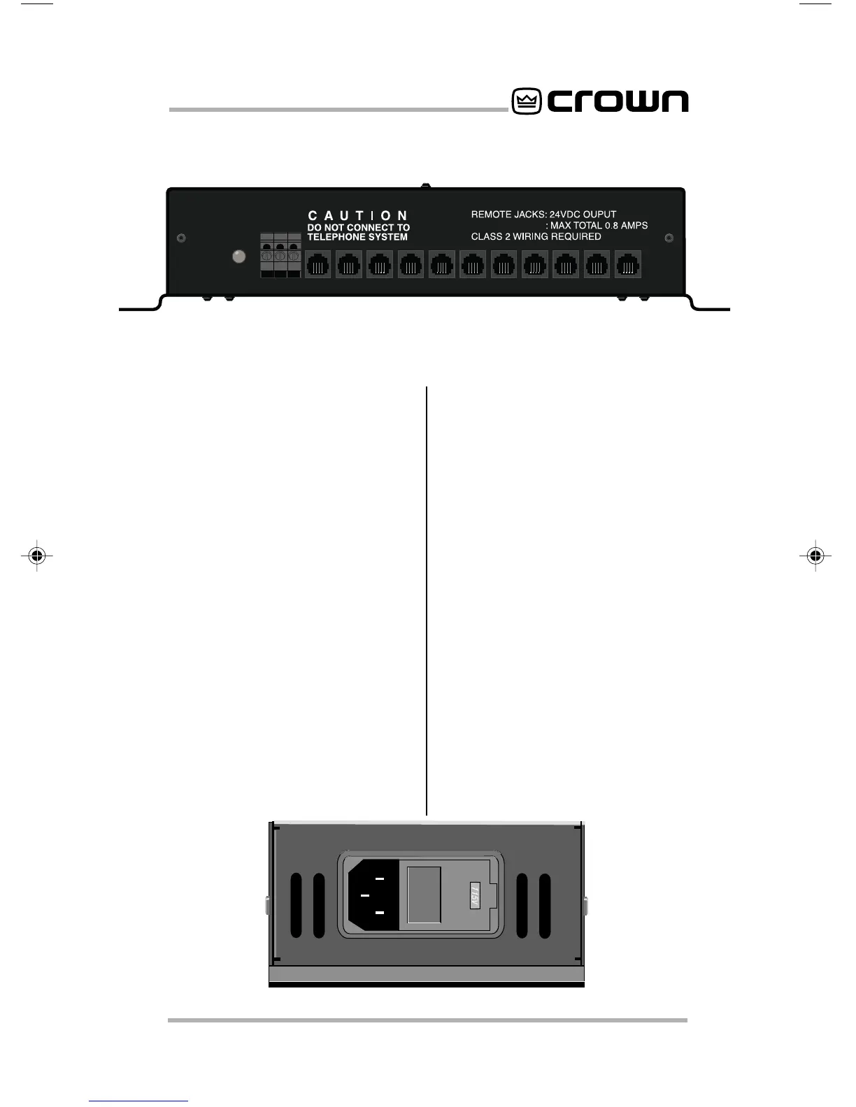
2 Facilities
A. Enable Light
Green LED located on the left side
panel that indicates low voltage sup-
ply operation.
B. On/Com/Off
On, common, and off barrier block
input located on the left front panel
for connection of remote momentary
switches.
C. Slave/Aux In Port
RJ-11 connector located on the left
side panel that allows control from an
IQ System aux port. Also used for
daisy-chaining
R.S.V.P.
units to-
gether.
D. To Amplifier Remote
RJ-11 connectors located on the left
and right side panels for connecting
to CT-10 series amplifiers or daisy-
chained
R.S.V.P.
units. (See Figures
3.2 and 3.3) Each
R.S.V.P.
can con-
trol 21 separate CT-10 series amplifi-
ers, or the
R.S.V.P.
can be
daisy-chained to other
R.S.V.P.
units
to provide control over an unlimited
number of amplifiers. RJ-11 connec-
tors are available from the Crown
Parts Department (219-294-8200).
E. AC Power Inlet
Standard IEC “three prong” AC con-
nector located on the back panel.
F. Fuse Access Door
Located on the back panel, this al-
lows access to the fuse in the event
that it needs to be changed. Please
refer to section 7.1 on changing the
fuse before trying to access this
area.
Figure 2.1 Left Panel Facilities
Figure 2.2 Rear Panel Facilities
 Loading...