R.S.V.P. Remote Switching Voltage Provider
Page 6
3 Installation
This section will give the necessary
information for installing the
R.S.V.P.
into your equipment rack. It will also
provide ways to incorporate the
R.S.V.P.
into your system. Please
read this section thoroughly, as the
R.S.V.P.
has special cooling and
mounting requirements.
3.1 Cooling
Make sure that the vent holes of
the
R.S.V.P.
are NOT obstructed.
When mounting the unit in the back
of your rack, avoid blocking air flow
to all of your rack-mounted equip-
ment
.
3.2 Mounting
The
R.S.V.P.
is designed to be
mounted in the REAR of a standard
19-inch (48.3-cm) equipment rack.
Placing it in the back of the rack pro-
vides a more tamper-resistant loca-
tion and allows for easier access to
equipment. Four keyholes on the unit
can accomodate up to a #10 screw.
For a more secure installation, four
0.2- inch (0.5-cm) holes are also
available.
.
3.3 Wiring for Amplifiers
Convenient RJ-11 connectors link
the
R.S.V.P.
to the remote CT-10 se-
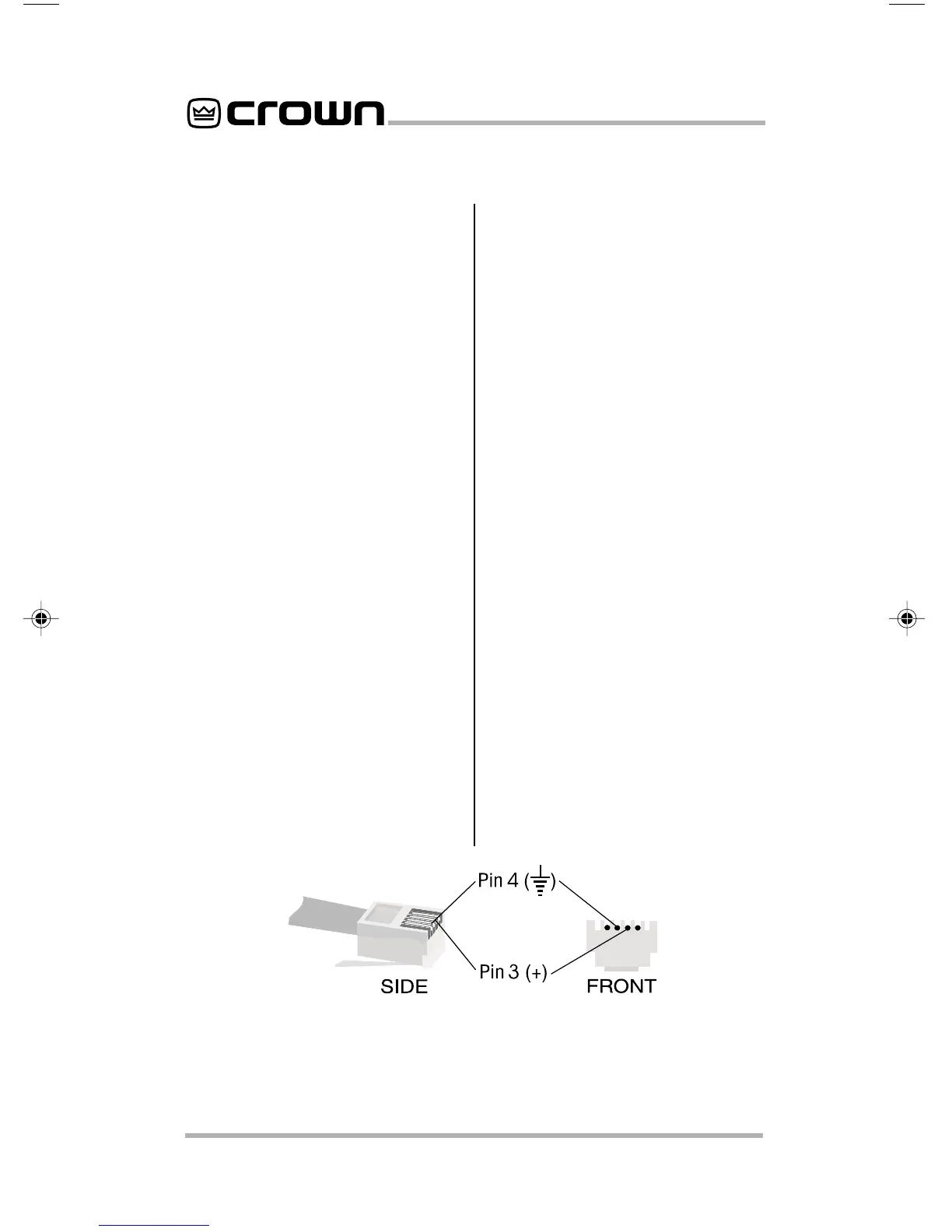
ries amplifiers. Please note that the
RJ-11 jacks are polarity sensitive. Pin
4 must be grounded, and Pin 3 must
be supplied with a positive voltage
pull up (positive with respect to
ground). Refer to Figure 3.1 for RJ
jack pin assignments.* The maxi-
mum signal that can be exposed to
the RJ-11 jacks is 35 VDC or 25 VAC.
(RJ-11 connectors are available from
the Crown Parts Department.)
Figure 3.2 shows one possible sys-
tem configuration using the
R.S.V.P.
and a rack of CT-10 series amplifiers.
Runs of less than 30 feet (9.15
meters) between the
R.S.V.P.
and
the amplifiers are required for the
R.S.V.P.
to function properly. Up to
21 CT-10 series amplifiers can be
controlled from a single
R.S.V.P.
However, daisy- chaining together
units, as shown in Figure 3.3, can
provide for an unlimited number of
amplifiers in a system.
* The mating connector for the
R.S.V.P.
RJ-11 jack contains 4 contact pins in a 6-slot
case, as shown. For additional information please contact your local dealer or
Crown Technical Support.
Figure 3.1 RJ-11 connector pin assignments
 Loading...